2021-05-18 12:21:48 +00:00
|
|
|
---
|
|
|
|
|
title: ThinkPad T60 Recovery guide
|
|
|
|
|
x-toc-enable: true
|
|
|
|
|
...
|
|
|
|
|
|
2024-01-27 22:35:38 +00:00
|
|
|
NOTE: Libreboot standardises on [flashprog](https://flashprog.org/wiki/Flashprog)
|
|
|
|
|
now, as of 27 January 2024, which is a fork of flashrom.
|
|
|
|
|
|
2021-05-18 12:21:48 +00:00
|
|
|
This section documents how to recover from a bad flash that prevents
|
|
|
|
|
your ThinkPad T60 from booting.
|
|
|
|
|
|
|
|
|
|
This section documents how to recover from a bad flash that prevents
|
|
|
|
|
your ThinkPad X60 from booting.
|
|
|
|
|
|
2022-11-14 02:31:12 +00:00
|
|
|
ROM images for this machine are well-tested in libreboot, so bricks are rare.
|
2021-05-18 12:21:48 +00:00
|
|
|
The most common cause of a brick is operator error, when flashing a ROM image.
|
|
|
|
|
In *most* cases, the cause will be that there is no bootblock, or an invalid
|
|
|
|
|
one.
|
|
|
|
|
|
|
|
|
|
Brick type 1: bucts not reset. {#bucts_brick}
|
|
|
|
|
==============================
|
|
|
|
|
|
2022-11-14 02:31:12 +00:00
|
|
|
You still have Lenovo BIOS, or you had libreboot running and you flashed
|
2021-05-18 12:21:48 +00:00
|
|
|
another ROM; and you had bucts 1 set and the ROM wasn't dd'd.\* or if
|
2022-11-14 02:31:12 +00:00
|
|
|
Lenovo BIOS was present and libreboot wasn't flashed.
|
2021-05-18 12:21:48 +00:00
|
|
|
|
|
|
|
|
There are *2* 64KiB bootblocks possible, in the upper part of the ROM image.
|
|
|
|
|
By default (bucts set to 0), the top one is used. If bucts is set to 1, the
|
|
|
|
|
lower one (the one before the top one) is used. This bootblock is the first
|
|
|
|
|
code that executes, during *romstage* as per coreboot hardware initialization.
|
|
|
|
|
|
|
|
|
|
BUC is short for *Backup Control* and TS is short for *Top Swap*. This is a
|
|
|
|
|
special register on Intel platforms. Lenovo BIOS sets PRx registers, preventing
|
|
|
|
|
software re-flashing, but there is a bug in the protection, allowing everything
|
|
|
|
|
*except* the upper 64KiB from being flashed. By default, coreboot only puts a
|
|
|
|
|
bootblock in the upper region. If you flash such a ROM, while bucts is set to 1,
|
|
|
|
|
the system won't boot because there's not a valid bootblock; this is common if
|
|
|
|
|
you're re-flashing when coreboot is already installed, and you didn't set bucts
|
|
|
|
|
back to 0.
|
|
|
|
|
|
|
|
|
|
When you install on X60/T60 the first time, you set this bucts bit to 1, then
|
|
|
|
|
you re-flash a second time and set it back to 0.
|
|
|
|
|
|
|
|
|
|
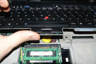
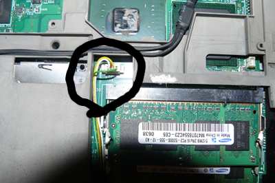
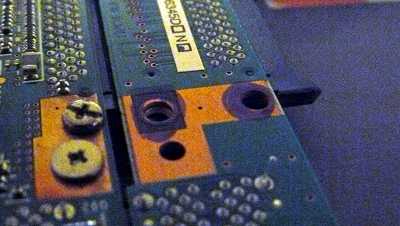
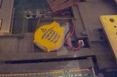
In this case, unbricking is easy: reset BUC.TS to 0 by removing that
|
|
|
|
|
yellow cmos coin (it's a battery) and putting it back after a minute or
|
|
|
|
|
two:\
|
|
|
|
|
|
|
|
|
|
|
|
|
|
|
\*Those dd commands should be applied to all newly compiled T60 ROM
|
2022-11-14 02:31:12 +00:00
|
|
|
images (the ROM images in libreboot binary archives already have this
|
2021-05-18 12:21:48 +00:00
|
|
|
applied!):
|
|
|
|
|
|
2023-01-08 01:22:04 +00:00
|
|
|
dd if=coreboot.rom of=top64k.bin bs=1 skip=$[$(stat -c %s coreboot.rom) - 0x10000] count=64k
|
|
|
|
|
dd if=coreboot.rom bs=1 skip=$[$(stat -c %s coreboot.rom) - 0x20000] count=64k | hexdump
|
|
|
|
|
dd if=top64k.bin of=coreboot.rom bs=1 seek=$[$(stat -c %s coreboot.rom) - 0x20000] count=64k conv=notrunc
|
2021-05-18 12:21:48 +00:00
|
|
|
|
|
|
|
|
(doing this makes the ROM suitable for use when flashing a system that
|
|
|
|
|
still has Lenovo BIOS running, using those instructions:
|
|
|
|
|
<http://www.coreboot.org/Board:lenovo/x60/Installation>. (it says x60,
|
|
|
|
|
but instructions for t60 are identical)
|
|
|
|
|
|
|
|
|
|
Brick type 2: bad ROM image {#recovery}
|
|
|
|
|
===========================================
|
|
|
|
|
|
|
|
|
|
In this instance, you might have flashed a ROM without the top bootblock copied
|
|
|
|
|
to the lower 64KiB section in the ROM, and you flashed the ROM for the first
|
|
|
|
|
time (from Lenovo BIOS), in which case there is not a valid bootblock.
|
|
|
|
|
|
|
|
|
|
In this scenario, you compiled a ROM that had an incorrect
|
|
|
|
|
configuration, or there is an actual bug preventing your system from
|
|
|
|
|
booting. Or, maybe, you set BUC.TS to 0 and shut down after first flash
|
|
|
|
|
while Lenovo BIOS was running. In any case, your system is bricked and
|
|
|
|
|
will not boot at all.
|
|
|
|
|
|
|
|
|
|
"Unbricking" means flashing a known-good (working) ROM. The problem:
|
|
|
|
|
you can't boot the system, making this difficult. In this situation,
|
|
|
|
|
external hardware (see hardware requirements above) is needed which can
|
2022-11-14 02:31:12 +00:00
|
|
|
flash the SPI chip (where libreboot resides).
|
2021-05-18 12:21:48 +00:00
|
|
|
|
|
|
|
|
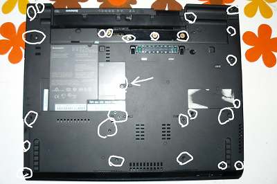
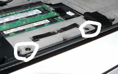
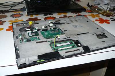
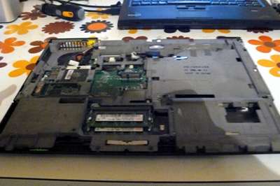
Remove those screws and remove the HDD:\
|
|
|
|
|
|
|
|
|
|
|
|
|
|
|
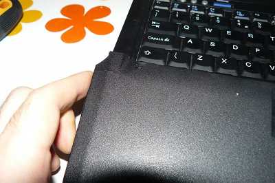
Lift off the palm rest:\
|
|
|
|
|
|
|
|
|
|
|
|
|
|
|
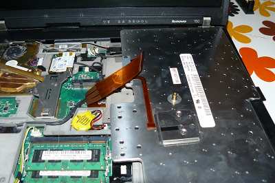
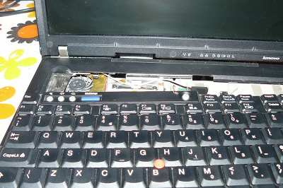
Lift up the keyboard, pull it back a bit, flip it over like that and
|
|
|
|
|
then disconnect it from the board:\
|
|
|
|
|
|
|
|
|
|

|
|
|
|
|
|
|
|
|
|
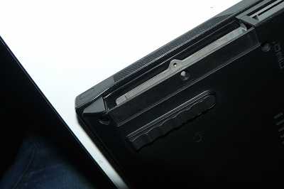
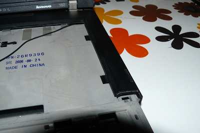
Gently wedge both sides loose:\
|
|
|
|
|
|
|
|
|
|
|
|
|
|
|
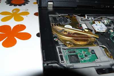
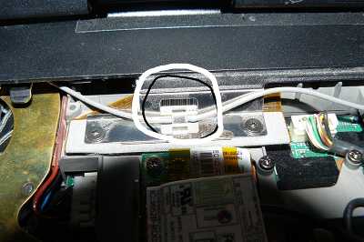
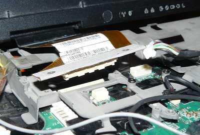
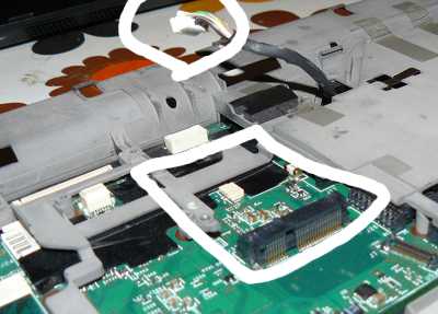
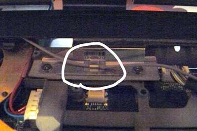
Remove that cable from the position:\
|
|
|
|
|
|
|
|
|
|
|
|
|
|
|
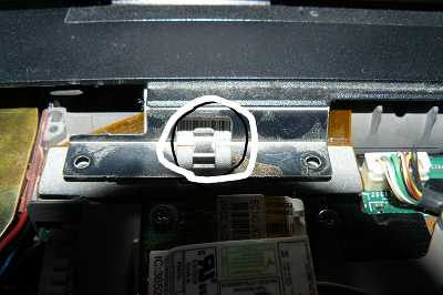
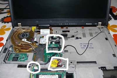
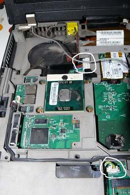
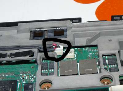
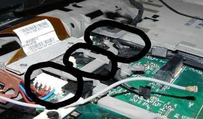
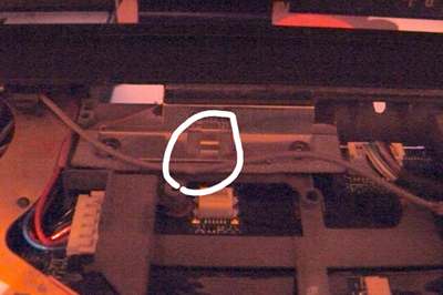
Now remove that bezel. Remove wifi, nvram battery and speaker connector
|
|
|
|
|
(also remove 56k modem, on the left of wifi):\
|
|
|
|
|
|
|
|
|
|
|
|
|
|
|
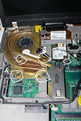
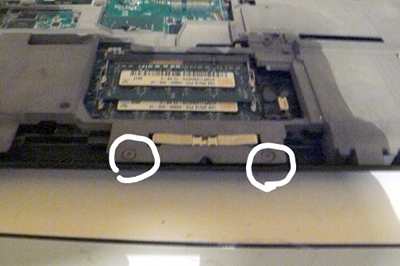
Remove those screws:\
|
|
|
|
|
|
|
|
|
|
|
|
|
|
|
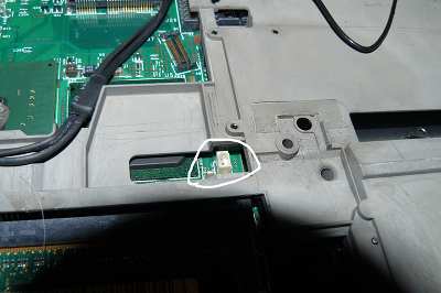
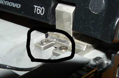
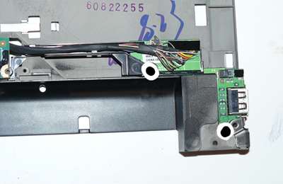
Disconnect the power jack:\
|
|
|
|
|
|
|
|
|
|
|
|
|
|
|
Remove nvram battery:\
|
|
|
|
|
|
|
|
|
|
|
|
|
|
|
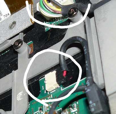
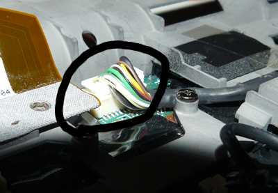
Disconnect cable (for 56k modem) and disconnect the other cable:\
|
|
|
|
|
|
|
|
|
|
|
|
|
|
|
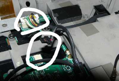
Disconnect speaker cable:\
|
|
|
|
|
|
|
|
|
|
|
|
|
|
|
Disconnect the other end of the 56k modem cable:\
|
|
|
|
|
|
|
|
|
|
|
|
|
|
|
Make sure you removed it:\
|
|
|
|
|
|
|
|
|
|
|
|
|
|
|
Unscrew those:\
|
|
|
|
|
|
|
|
|
|
|
|
|
|
|
Make sure you removed those:\
|
|
|
|
|
|
|
|
|
|
|
|
|
|
|
Disconnect LCD cable from board:\
|
|
|
|
|
|
|
|
|
|
|
|
|
|
|
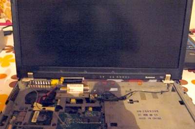
Remove those screws then remove the LCD assembly:\
|
|
|
|
|
|
|
|
|
|
|
|
|
|
|
|
|
|
|
|
Once again, make sure you removed those:\
|
|
|
|
|
|
|
|
|
|
|
|
|
|
|
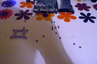
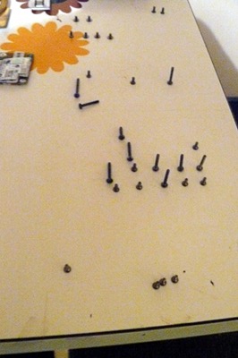
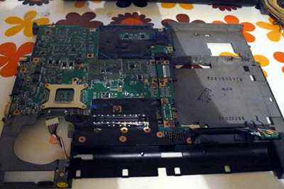
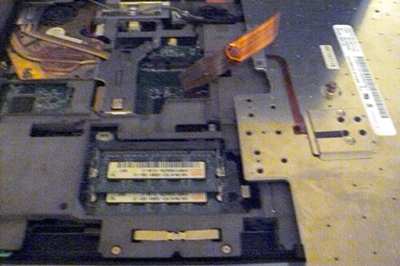
Remove the shielding containing the motherboard, then flip it over.
|
|
|
|
|
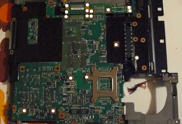
Remove these screws, placing them on a steady surface in the same layout
|
|
|
|
|
as they were in before you removed them. Also, you should mark each
|
|
|
|
|
screw hole after removing the screw (a permanent marker pen will do),
|
|
|
|
|
this is so that you have a point of reference when re-assembling the
|
|
|
|
|
system:
|
|
|
|
|
|
|
|
|
|
|
|
|
|
|
|
|
|
|
|
|
|
|
|
|
|
|
|
|
|
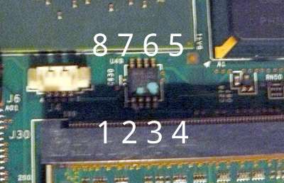
This photo shows the flash chip, near the RAM, with numbers of pins written:
|
|
|
|
|
|
|
|
|
|
|
|
|
|
|
|
|
|
|
|
Refer to the external flashing guide:
|
|
|
|
|
|
|
|
|
|
[Externally rewrite 25xx NOR flash via SPI protocol](spi.md)
|
|
|
|
|
|
|
|
|
|
NOTE: Do not use the 3.3v rail from your SPI programmer. Leave that disconnected.
|
|
|
|
|
For 3.3v, plug your charger into the mainboard (but do not power on the mainboard)
|
|
|
|
|
when the clip is connected. Before removing the clip, disconnect the charger.
|
|
|
|
|
This will provide adequate 3.3v DC at correct current levels. The SPI flash on an
|
|
|
|
|
X60 shares a common 3.3V rail with many other components on the mainboard,
|
|
|
|
|
which all draw a lot of current, more than your flasher can provide.
|
|
|
|
|
|
|
|
|
|
Example command:
|
|
|
|
|
|
2024-01-27 22:35:38 +00:00
|
|
|
sudo ./flashprog -p linux_spi:dev=/dev/spidev0.0,spispeed=4096 -w libreboot.rom -V
|
2021-05-18 12:21:48 +00:00
|
|
|
|
2024-01-27 22:35:38 +00:00
|
|
|
If flashprog complains about multiple flash chips detected, just pass the `-c`
|
2021-05-18 12:21:48 +00:00
|
|
|
option as it suggests, and pick any of the chips it lists. `spispeed=4096` or
|
|
|
|
|
lower (e.g. `spispeed=512`) is recommended on this board. The flashing becomes
|
|
|
|
|
unstable, on this machine, when you use higher speeds.
|
|
|
|
|
|
|
|
|
|
Reverse the steps to re-assemble your system, after you've flashed the chip.
|
|
|
|
|
|
2024-01-27 22:35:38 +00:00
|
|
|
It should be `Verifying flash... VERIFIED` at the end. If flashprog
|
2021-05-18 12:21:48 +00:00
|
|
|
complains about multiple flash chip definitions detected, then choose
|
|
|
|
|
one of them following the instructions in the output.
|
|
|
|
|
|
|
|
|
|
Put those screws back:\
|
|
|
|
|
|
|
|
|
|
|
|
|
|
|
Put it back into lower chassis:\
|
|
|
|
|
|
|
|
|
|
|
|
|
|
|
Attach LCD and insert screws (also, attach the lcd cable to the board):\
|
|
|
|
|
|
|
|
|
|
|
|
|
|
|
Insert those screws:\
|
|
|
|
|
|
|
|
|
|
|
|
|
|
|
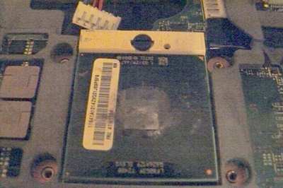
On the CPU (and there is another chip south-east to it, sorry forgot to
|
|
|
|
|
take pic) clean off the old thermal paste (with the alcohol) and apply
|
|
|
|
|
new (Artic Silver 5 is good, others are good too) you should also clean
|
|
|
|
|
the heatsink the same way\
|
|
|
|
|
|
|
|
|
|
|
|
|
|
|
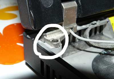
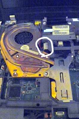
Attach the heatsink and install the screws (also, make sure to install
|
|
|
|
|
the AC jack as highlighted):\
|
|
|
|
|
|
|
|
|
|
|
|
|
|
|
Reinstall that upper bezel:\
|
|
|
|
|

|
|
|
|
|
|
|
|
|
|
Do that:\
|
|
|
|
|
|
|
|
|
|
|
|
|
|
|
Re-attach modem, wifi, (wwan?), and all necessary cables. Sorry, forgot
|
|
|
|
|
to take pics. Look at previous removal steps to see where they go back
|
|
|
|
|
to.
|
|
|
|
|
|
|
|
|
|
Attach keyboard and install nvram battery:\
|
|
|
|
|
|
|
|
|
|
|
|
|
|
|
Place keyboard and (sorry, forgot to take pics) reinstall the palmrest
|
|
|
|
|
and insert screws on the underside:\
|
|
|
|
|
|
|
|
|
|
|
|
|
|
|
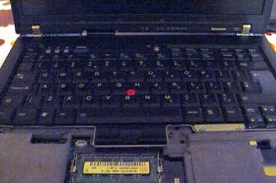
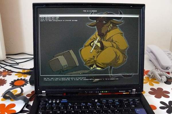
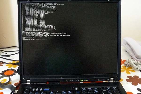
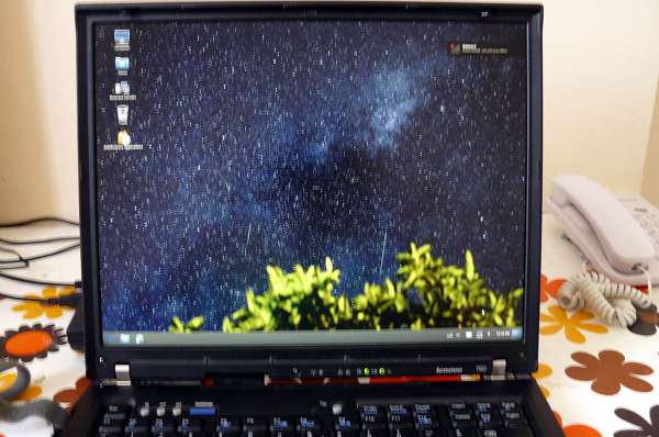
It lives!\
|
|
|
|
|
|
|
|
|
|
|
|
|
|
|
|
|
|
|
|
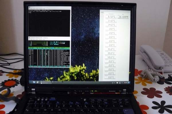
Always stress test ('stress -c 2' and xsensors. below 90C is ok) when
|
|
|
|
|
replacing cpu paste/heatsink:\
|
|
|
|
|
|