2021-05-18 12:21:48 +00:00
|
|
|
---
|
|
|
|
|
title: ThinkPad X60 Recovery guide
|
|
|
|
|
x-toc-enable: true
|
|
|
|
|
...
|
|
|
|
|
|
|
|
|
|
This section documents how to recover from a bad flash that prevents
|
|
|
|
|
your ThinkPad X60 from booting.
|
|
|
|
|
|
2022-11-14 02:31:12 +00:00
|
|
|
ROM images for this machine are well-tested in libreboot, so bricks are rare.
|
2021-05-18 12:21:48 +00:00
|
|
|
The most common cause of a brick is operator error, when flashing a ROM image.
|
|
|
|
|
In *most* cases, the cause will be that there is no bootblock, or an invalid
|
|
|
|
|
one.
|
|
|
|
|
|
|
|
|
|
Brick type 1: bucts not reset. {#bucts_brick}
|
|
|
|
|
==============================
|
|
|
|
|
|
2022-11-14 02:31:12 +00:00
|
|
|
You still have Lenovo BIOS, or you had libreboot running and you flashed
|
2021-05-18 12:21:48 +00:00
|
|
|
another ROM; and you had bucts 1 set and the ROM wasn't dd'd.\* or if
|
2022-11-14 02:31:12 +00:00
|
|
|
Lenovo BIOS was present and libreboot wasn't flashed.
|
2021-05-18 12:21:48 +00:00
|
|
|
|
|
|
|
|
There are *2* 64KiB bootblocks possible, in the upper part of the ROM image.
|
|
|
|
|
By default (bucts set to 0), the top one is used. If bucts is set to 1, the
|
|
|
|
|
lower one (the one before the top one) is used. This bootblock is the first
|
|
|
|
|
code that executes, during *romstage* as per coreboot hardware initialization.
|
|
|
|
|
|
|
|
|
|
BUC is short for *Backup Control* and TS is short for *Top Swap*. This is a
|
|
|
|
|
special register on Intel platforms. Lenovo BIOS sets PRx registers, preventing
|
|
|
|
|
software re-flashing, but there is a bug in the protection, allowing everything
|
|
|
|
|
*except* the upper 64KiB from being flashed. By default, coreboot only puts a
|
|
|
|
|
bootblock in the upper region. If you flash such a ROM, while bucts is set to 1,
|
|
|
|
|
the system won't boot because there's not a valid bootblock; this is common if
|
|
|
|
|
you're re-flashing when coreboot is already installed, and you didn't set bucts
|
|
|
|
|
back to 0.
|
|
|
|
|
|
|
|
|
|
When you install on X60/T60 the first time, you set this bucts bit to 1, then
|
|
|
|
|
you re-flash a second time and set it back to 0.
|
|
|
|
|
|
|
|
|
|
In this case, unbricking is easy: reset BUC.TS to 0 by removing that
|
|
|
|
|
yellow cmos coin (it's a battery) and putting it back after a minute or
|
|
|
|
|
two:\
|
|
|
|
|
\
|
|
|
|
|
|
|
|
|
|
\*Those dd commands should be applied to all newly compiled X60 ROM
|
2022-11-14 02:31:12 +00:00
|
|
|
images (the ROM images in libreboot binary archives already have this
|
2021-05-18 12:21:48 +00:00
|
|
|
applied!):
|
|
|
|
|
|
|
|
|
|
dd if=coreboot.rom of=top64k.bin bs=1 skip=$[$(stat -c %s coreboot.rom) - 0x10000] count=64k
|
|
|
|
|
dd if=coreboot.rom bs=1 skip=$[$(stat -c %s coreboot.rom) - 0x20000] count=64k | hexdump
|
|
|
|
|
dd if=top64k.bin of=coreboot.rom bs=1 seek=$[$(stat -c %s coreboot.rom) - 0x20000] count=64k conv=notrunc
|
|
|
|
|
|
|
|
|
|
(doing this makes the ROM suitable for use when flashing a system that
|
|
|
|
|
still has Lenovo BIOS running, using those instructions:
|
|
|
|
|
<http://www.coreboot.org/Board:lenovo/x60/Installation>.
|
|
|
|
|
|
|
|
|
|
Brick type 2: bad ROM image {#recovery}
|
|
|
|
|
===========================================
|
|
|
|
|
|
|
|
|
|
In this instance, you might have flashed a ROM without the top bootblock copied
|
|
|
|
|
to the lower 64KiB section in the ROM, and you flashed the ROM for the first
|
|
|
|
|
time (from Lenovo BIOS), in which case there is not a valid bootblock.
|
|
|
|
|
|
|
|
|
|
In this scenario, you compiled a ROM that had an incorrect
|
|
|
|
|
configuration, or there is an actual bug preventing your system from
|
|
|
|
|
booting. Or, maybe, you set BUC.TS to 0 and shut down after first flash
|
|
|
|
|
while Lenovo BIOS was running. In any case, your system is bricked and
|
|
|
|
|
will not boot at all.
|
|
|
|
|
|
|
|
|
|
"Unbricking" means flashing a known-good (working) ROM. The problem:
|
|
|
|
|
you can't boot the system, making this difficult. In this situation,
|
|
|
|
|
external hardware (see hardware requirements above) is needed which can
|
2022-11-14 02:31:12 +00:00
|
|
|
flash the SPI chip (where libreboot resides).
|
2021-05-18 12:21:48 +00:00
|
|
|
|
|
|
|
|
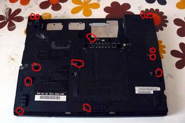
Remove those screws:\
|
|
|
|
|
|
|
|
|
|
|
|
|
|
|
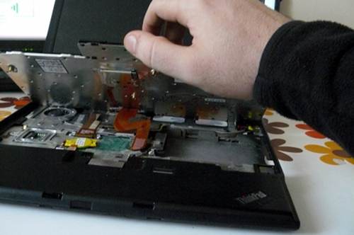
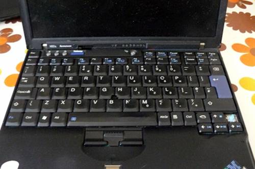
Push the keyboard forward (carefully):\
|
|
|
|
|

|
|
|
|
|
|
|
|
|
|
Lift the keyboard up and disconnect it from the board:\
|
|
|
|
|
|
|
|
|
|
|
|
|
|
|
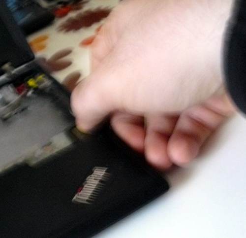
Grab the right-hand side of the chassis and force it off (gently) and
|
|
|
|
|
pry up the rest of the chassis:\
|
|
|
|
|
|
|
|
|
|
|
|
|
|
|
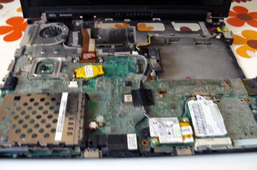
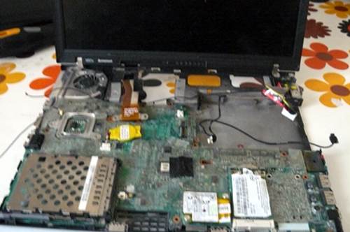
You should now have this:\
|
|
|
|
|

|
|
|
|
|
|
|
|
|
|
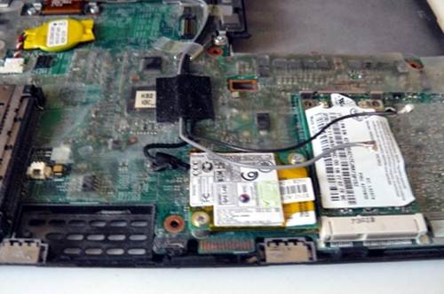
Disconnect the wifi antenna cables, the modem cable and the speaker:\
|
|
|
|
|
|
|
|
|
|
|
|
|
|
|
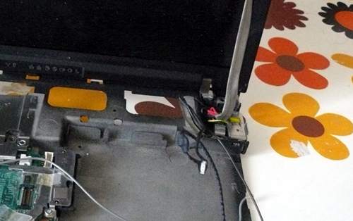
Unroute the cables along their path, carefully lifting the tape that
|
|
|
|
|
holds them in place. Then, disconnect the modem cable (other end) and
|
|
|
|
|
power connection and unroute all the cables so that they dangle by the
|
|
|
|
|
monitor hinge on the right-hand side:\
|
|
|
|
|
|
|
|
|
|
|
|
|
|
|
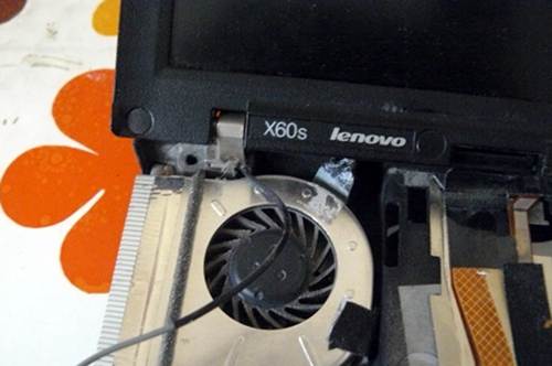
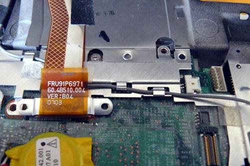
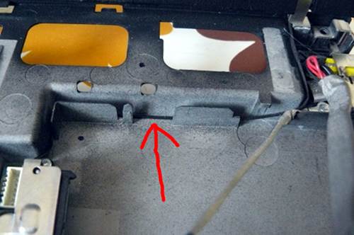
Disconnect the monitor from the motherboard, and unroute the grey
|
|
|
|
|
antenna cable, carefully lifting the tape that holds it into place:\
|
|
|
|
|
|
|
|
|
|
|
|
|
|
|
Carefully lift the remaining tape and unroute the left antenna cable so
|
|
|
|
|
that it is loose:\
|
|
|
|
|
|
|
|
|
|
|
|
|
|
|
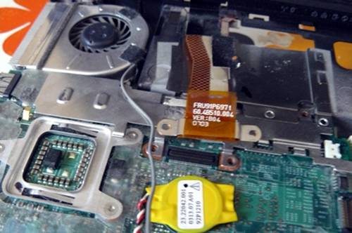
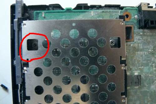
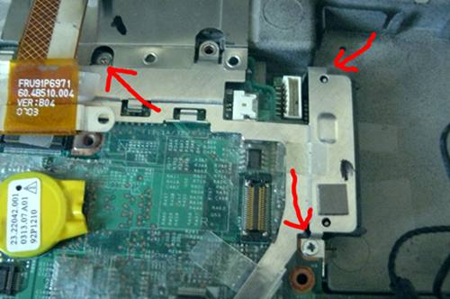
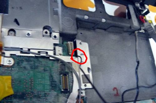
Remove the screw that is highlighted (do NOT remove the other one; it
|
|
|
|
|
holds part of the heatsink (other side) into place):\
|
|
|
|
|
|
|
|
|
|
|
|
|
|
|
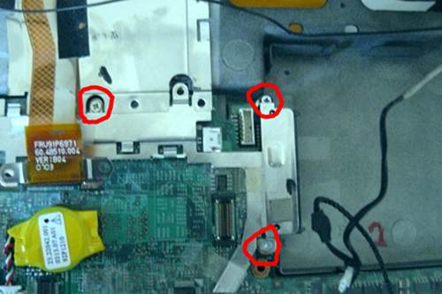
Remove those screws:\
|
|
|
|
|
|
|
|
|
|
|
|
|
|
|
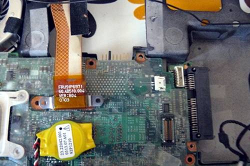
Carefully remove the plate, like so:\
|
|
|
|
|
|
|
|
|
|
|
|
|
|
|
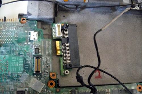
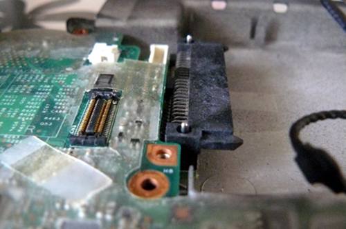
Remove the SATA connector:\
|
|
|
|
|
|
|
|
|
|
|
|
|
|
|
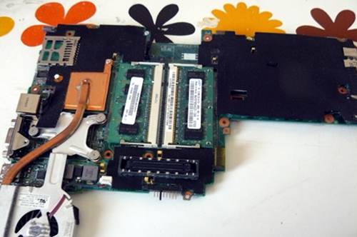
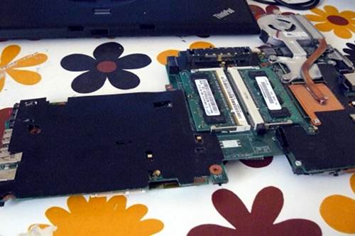
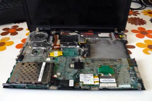
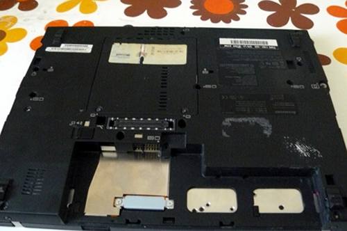
Now remove the motherboard (gently) and cast the lcd/chassis aside:\
|
|
|
|
|
|
|
|
|
|
|
|
|
|
|
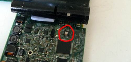
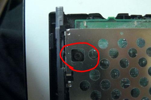
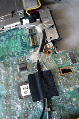
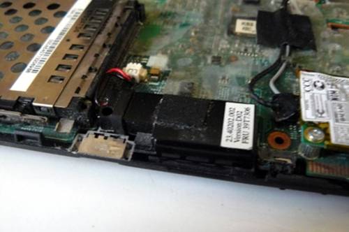
Lift back that tape and hold it with something. Highlighted is the SPI
|
|
|
|
|
flash chip:\
|
|
|
|
|
|
|
|
|
|
|
|
|
|
|
Here is another photo, with the numbers of the pins written:\
|
|
|
|
|
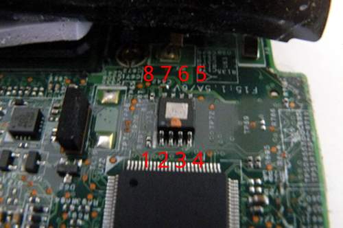\
|
|
|
|
|
|
|
|
|
|
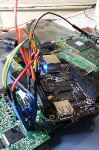
This photo shows an SPI flasher used, with SOIC8 test clip:\
|
|
|
|
|
|
|
|
|
|
|
|
|
|
|
Refer to the following guide:\
|
|
|
|
|
[Externally rewrite 25xx NOR flash via SPI protocol](spi.md)
|
|
|
|
|
|
|
|
|
|
NOTE: Do not use the 3.3v rail from your raspberry pi. Leave that disconnected.
|
|
|
|
|
For 3.3v, plug your charger into the mainboard (but do not power on the mainboard)
|
|
|
|
|
when the clip is connected. Before removing the clip, disconnect the charger.
|
|
|
|
|
This will provide adequate 3.3v DC at correct current levels. The SPI flash on an
|
|
|
|
|
X60 shares a common 3.3V rail with many other components on the mainboard,
|
|
|
|
|
which all draw a lot of current, more than your programmer can provide.
|
|
|
|
|
|
|
|
|
|
Example RPi command:
|
|
|
|
|
|
2022-11-14 02:31:12 +00:00
|
|
|
sudo ./flashrom -p linux_spi:dev=/dev/spidev0.0,spispeed=4096 -w libreboot.rom -V
|
2021-05-18 12:21:48 +00:00
|
|
|
|
|
|
|
|
If flashrom complains about multiple flash chips detected, just pass the `-c`
|
|
|
|
|
option as it suggests, and pick any of the chips it lists. `spispeed=4096` or
|
|
|
|
|
lower (e.g. `spispeed=512`) is recommended on this board. The flashing becomes
|
|
|
|
|
unstable, on this machine, when you use higher speeds.
|
|
|
|
|
|
|
|
|
|
Reverse the steps to re-assemble your system, after you've flashed the chip.
|
|
|
|
|
|
|
|
|
|
It should be `Verifying flash... VERIFIED` at the end. If flashrom
|
|
|
|
|
complains about multiple flash chip definitions detected, then choose
|
|
|
|
|
one of them following the instructions in the output.
|
|
|
|
|
|
|
|
|
|
Remove the programmer and put it away somewhere. Put back the tape and
|
|
|
|
|
press firmly over it:\
|
|
|
|
|
|
|
|
|
|
|
|
|
|
|
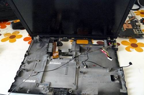
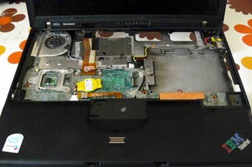
Your empty chassis:\
|
|
|
|
|
|
|
|
|
|
|
|
|
|
|
Put the motherboard back in:\
|
|
|
|
|
|
|
|
|
|
|
|
|
|
|
Reconnect SATA:\
|
|
|
|
|
|
|
|
|
|
|
|
|
|
|
Put the plate back and re-insert those screws:\
|
|
|
|
|
|
|
|
|
|
|
|
|
|
|
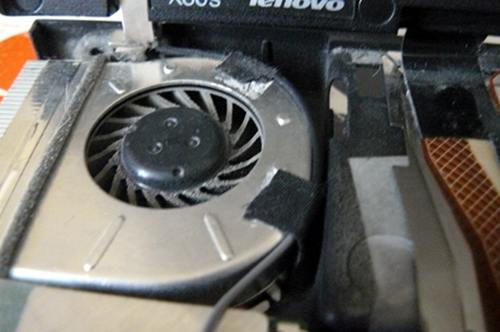
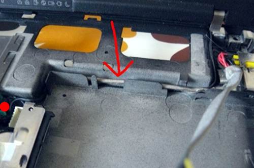
Re-route that antenna cable around the fan and apply the tape:\
|
|
|
|
|
|
|
|
|
|
|
|
|
|
|
Route the cable here and then (not shown, due to error on my part)
|
|
|
|
|
reconnect the monitor cable to the motherboard and re-insert the
|
|
|
|
|
screws:\
|
|
|
|
|
|
|
|
|
|
|
|
|
|
|
Re-insert that screw:\
|
|
|
|
|
|
|
|
|
|
|
|
|
|
|
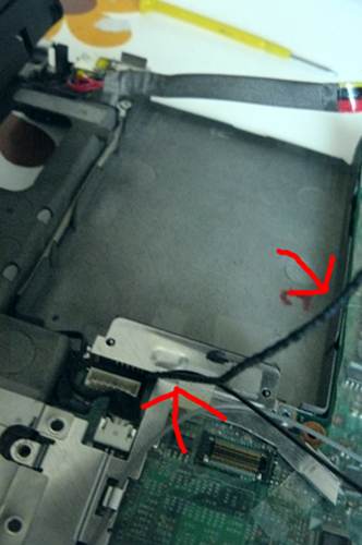
Route the black antenna cable like so:\
|
|
|
|
|
|
|
|
|
|
|
|
|
|
|
Tuck it in neatly like so:\
|
|
|
|
|
|
|
|
|
|
|
|
|
|
|
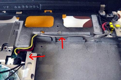
Route the modem cable like so:\
|
|
|
|
|
|
|
|
|
|
|
|
|
|
|
Connect modem cable to board and tuck it in neatly like so:\
|
|
|
|
|
|
|
|
|
|
|
|
|
|
|
Route the power connection and connect it to the board like so:\
|
|
|
|
|
|
|
|
|
|
|
|
|
|
|
Route the antenna and modem cables neatly like so:\
|
|
|
|
|
|
|
|
|
|
|
|
|
|
|
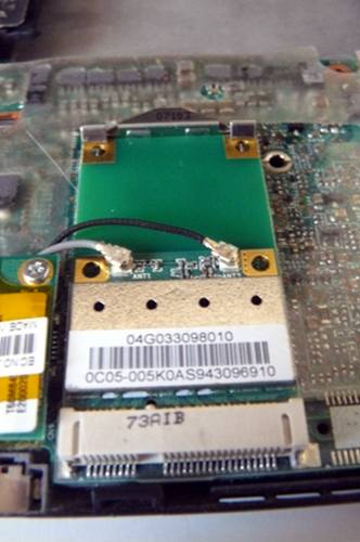
Connect the wifi antenna cables. At the start of the tutorial, this
|
|
|
|
|
system had an Intel wifi chip. Here you see I've replaced it with an
|
|
|
|
|
Atheros AR5B95 (supports 802.11n and can be used without blobs):\
|
|
|
|
|
|
|
|
|
|
|
|
|
|
|
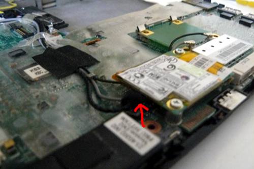
Connect the modem cable:\
|
|
|
|
|
|
|
|
|
|
|
|
|
|
|
Connect the speaker:\
|
|
|
|
|
|
|
|
|
|
|
|
|
|
|
You should now have this:\
|
|
|
|
|
|
|
|
|
|
|
|
|
|
|
Re-connect the upper chassis:\
|
|
|
|
|
|
|
|
|
|
|
|
|
|
|
Re-connect the keyboard:\
|
|
|
|
|
|
|
|
|
|
|
|
|
|
|
Re-insert the screws that you removed earlier:\
|
|
|
|
|
|
|
|
|
|
|
|
|
|
|
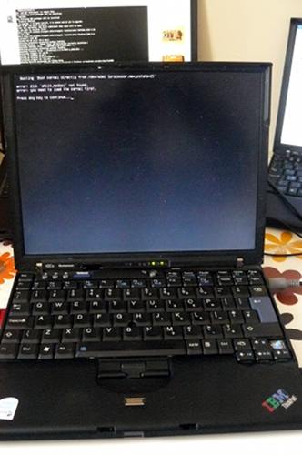
Power on!\
|
|
|
|
|
|
|
|
|
|
|
|
|
|
|
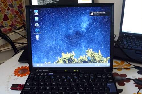
Operating system:\
|
|
|
|
|
|