2021-05-18 12:21:48 +00:00
|
|
|
---
|
|
|
|
|
title: ThinkPad X60 Recovery guide
|
|
|
|
|
x-toc-enable: true
|
|
|
|
|
...
|
|
|
|
|
|
2024-08-26 02:47:30 +00:00
|
|
|
NOTE: Libreboot standardises on [flashprog](https://flashprog.org/wiki/Flashprog)
|
|
|
|
|
now, as of 27 January 2024, which is a fork of flashrom.
|
2021-05-18 12:21:48 +00:00
|
|
|
|
|
|
|
|
"Unbricking" means flashing a known-good (working) ROM. The problem:
|
|
|
|
|
you can't boot the system, making this difficult. In this situation,
|
2024-08-26 02:47:30 +00:00
|
|
|
external hardware is needed which can flash the SPI chip (where libreboot
|
|
|
|
|
resides). First, disassemble the machine using the following steps, and refer
|
|
|
|
|
to the external flashing guide linked later from *this* guide.
|
2021-05-18 12:21:48 +00:00
|
|
|
|
|
|
|
|
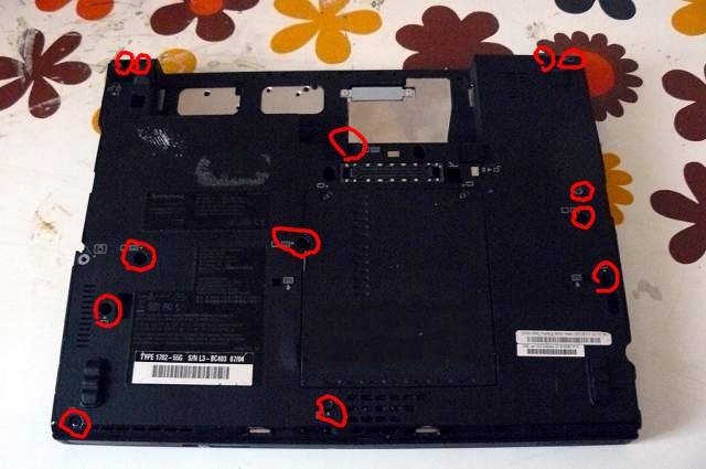
Remove those screws:\
|
|
|
|
|
|
|
|
|
|
|
|
|
|
|
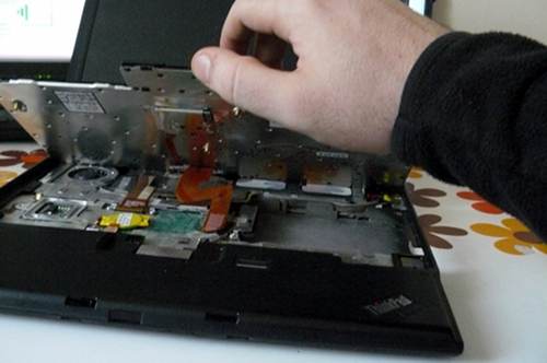
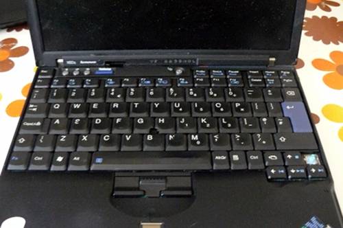
Push the keyboard forward (carefully):\
|
|
|
|
|

|
|
|
|
|
|
|
|
|
|
Lift the keyboard up and disconnect it from the board:\
|
|
|
|
|
|
|
|
|
|
|
|
|
|
|
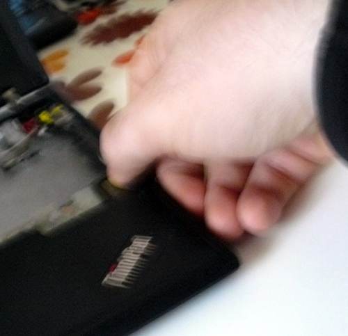
Grab the right-hand side of the chassis and force it off (gently) and
|
|
|
|
|
pry up the rest of the chassis:\
|
|
|
|
|
|
|
|
|
|
|
|
|
|
|
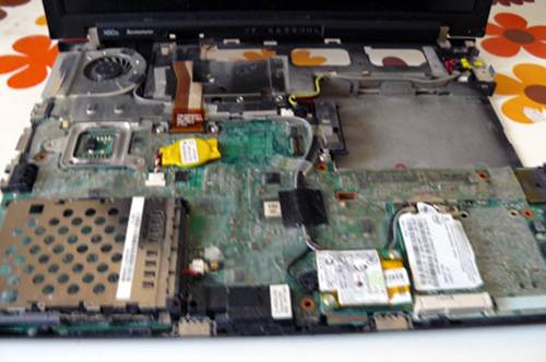
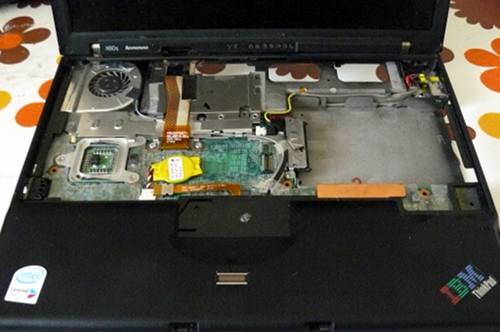
You should now have this:\
|
|
|
|
|
|
|
|
|
|
|
|
|
|
|
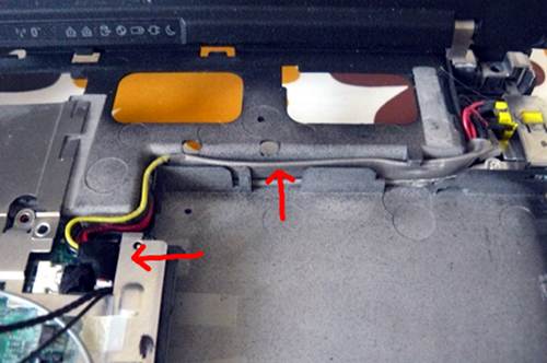
Disconnect the wifi antenna cables, the modem cable and the speaker:\
|
|
|
|
|
|
|
|
|
|
|
|
|
|
|
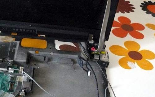
Unroute the cables along their path, carefully lifting the tape that
|
|
|
|
|
holds them in place. Then, disconnect the modem cable (other end) and
|
|
|
|
|
power connection and unroute all the cables so that they dangle by the
|
|
|
|
|
monitor hinge on the right-hand side:\
|
|
|
|
|
|
|
|
|
|
|
|
|
|
|
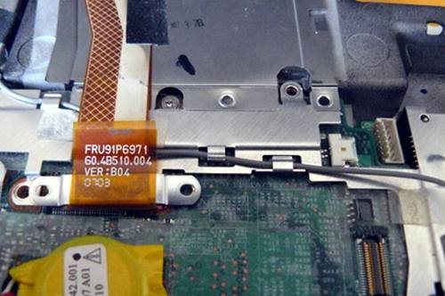
Disconnect the monitor from the motherboard, and unroute the grey
|
|
|
|
|
antenna cable, carefully lifting the tape that holds it into place:\
|
|
|
|
|
|
|
|
|
|
|
|
|
|
|
Carefully lift the remaining tape and unroute the left antenna cable so
|
|
|
|
|
that it is loose:\
|
|
|
|
|
|
|
|
|
|
|
|
|
|
|
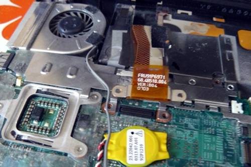
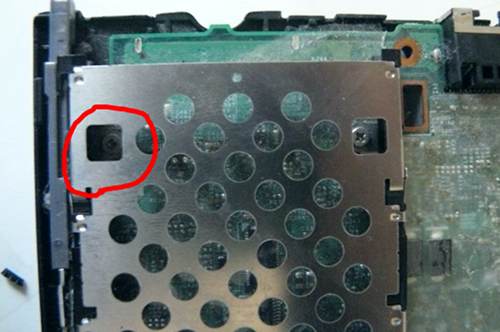
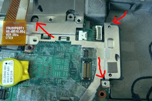
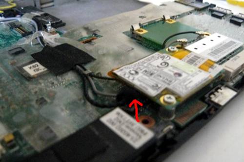
Remove the screw that is highlighted (do NOT remove the other one; it
|
|
|
|
|
holds part of the heatsink (other side) into place):\
|
|
|
|
|
|
|
|
|
|
|
|
|
|
|
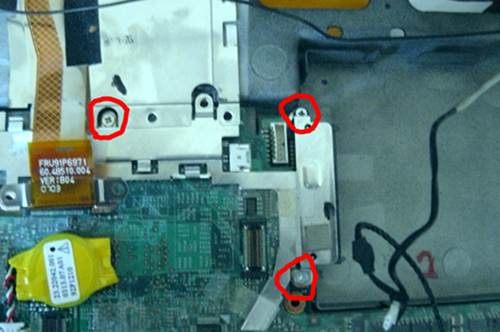
Remove those screws:\
|
|
|
|
|
|
|
|
|
|
|
|
|
|
|
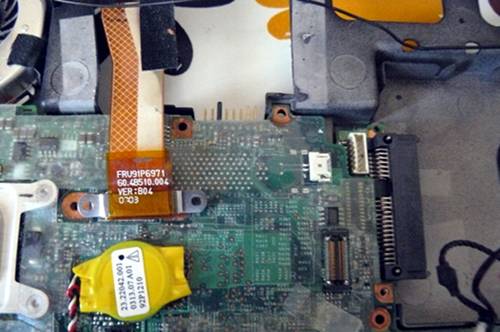
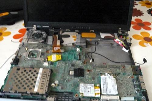
Carefully remove the plate, like so:\
|
|
|
|
|
|
|
|
|
|
|
|
|
|
|
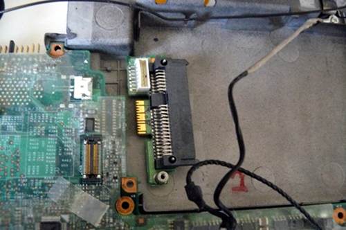
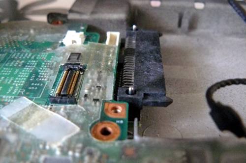
Remove the SATA connector:\
|
|
|
|
|
|
|
|
|
|
|
|
|
|
|
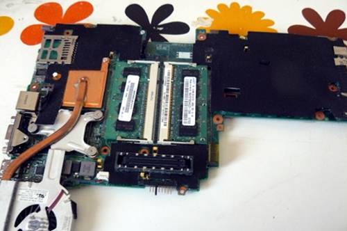
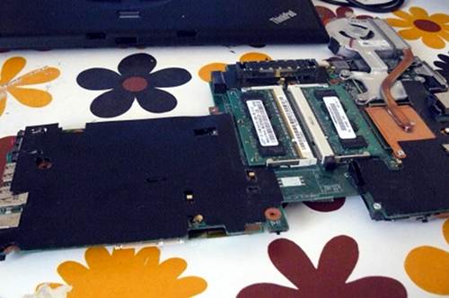
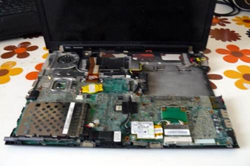
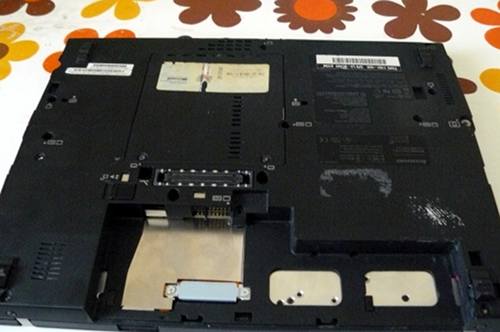
Now remove the motherboard (gently) and cast the lcd/chassis aside:\
|
|
|
|
|
|
|
|
|
|
|
|
|
|
|
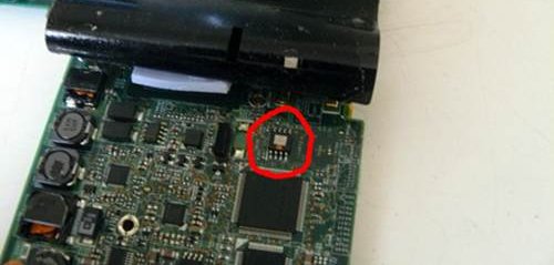
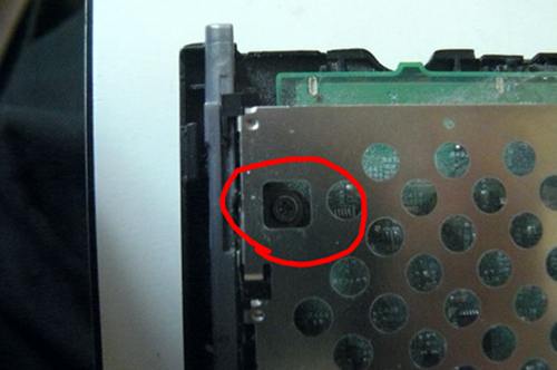
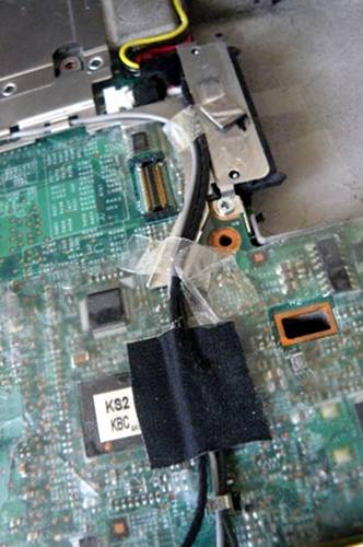
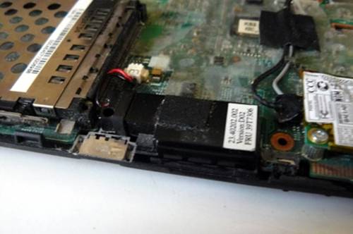
Lift back that tape and hold it with something. Highlighted is the SPI
|
|
|
|
|
flash chip:\
|
|
|
|
|
|
|
|
|
|
|
|
|
|
|
Here is another photo, with the numbers of the pins written:\
|
|
|
|
|
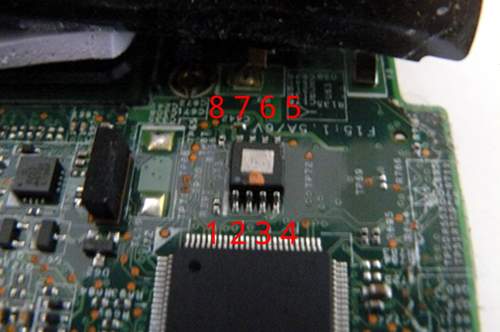\
|
|
|
|
|
|
|
|
|
|
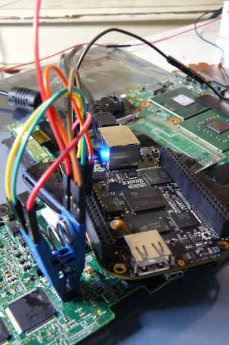
This photo shows an SPI flasher used, with SOIC8 test clip:\
|
|
|
|
|
|
|
|
|
|
|
|
|
|
|
Refer to the following guide:\
|
|
|
|
|
[Externally rewrite 25xx NOR flash via SPI protocol](spi.md)
|
|
|
|
|
|
|
|
|
|
NOTE: Do not use the 3.3v rail from your raspberry pi. Leave that disconnected.
|
|
|
|
|
For 3.3v, plug your charger into the mainboard (but do not power on the mainboard)
|
|
|
|
|
when the clip is connected. Before removing the clip, disconnect the charger.
|
|
|
|
|
This will provide adequate 3.3v DC at correct current levels. The SPI flash on an
|
|
|
|
|
X60 shares a common 3.3V rail with many other components on the mainboard,
|
|
|
|
|
which all draw a lot of current, more than your programmer can provide.
|
|
|
|
|
|
2023-03-03 05:44:56 +00:00
|
|
|
When you're finished flashing, remove the programmer and put it away somewhere.
|
|
|
|
|
Put back the tape and press firmly over it:\
|
2021-05-18 12:21:48 +00:00
|
|
|
|
|
|
|
|
|
|
|
|
|
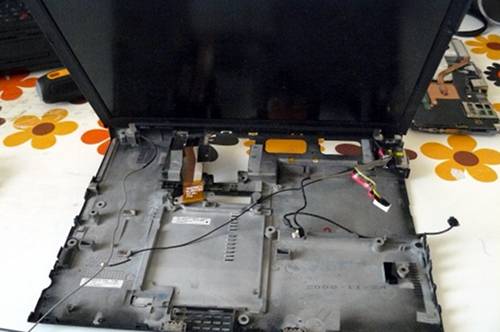
Your empty chassis:\
|
|
|
|
|
|
|
|
|
|
|
|
|
|
|
Put the motherboard back in:\
|
|
|
|
|
|
|
|
|
|
|
|
|
|
|
Reconnect SATA:\
|
|
|
|
|
|
|
|
|
|
|
|
|
|
|
Put the plate back and re-insert those screws:\
|
|
|
|
|
|
|
|
|
|
|
|
|
|
|
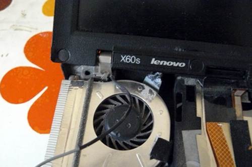
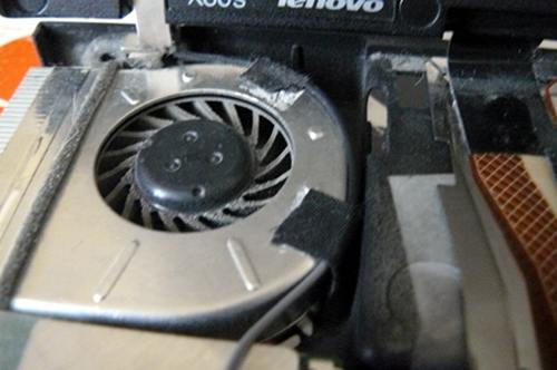
Re-route that antenna cable around the fan and apply the tape:\
|
|
|
|
|
|
|
|
|
|
|
|
|
|
|
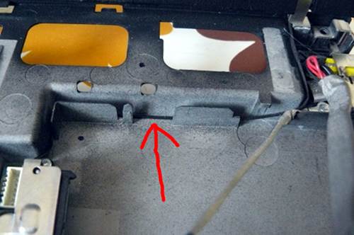
Route the cable here and then (not shown, due to error on my part)
|
|
|
|
|
reconnect the monitor cable to the motherboard and re-insert the
|
|
|
|
|
screws:\
|
|
|
|
|
|
|
|
|
|
|
|
|
|
|
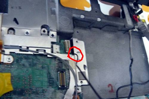
Re-insert that screw:\
|
|
|
|
|
|
|
|
|
|
|
|
|
|
|
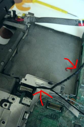
Route the black antenna cable like so:\
|
|
|
|
|
|
|
|
|
|
|
|
|
|
|
Tuck it in neatly like so:\
|
|
|
|
|
|
|
|
|
|
|
|
|
|
|
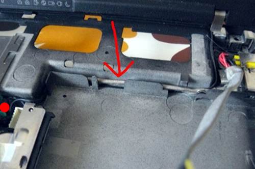
Route the modem cable like so:\
|
|
|
|
|
|
|
|
|
|
|
|
|
|
|
Connect modem cable to board and tuck it in neatly like so:\
|
|
|
|
|
|
|
|
|
|
|
|
|
|
|
Route the power connection and connect it to the board like so:\
|
|
|
|
|
|
|
|
|
|
|
|
|
|
|
Route the antenna and modem cables neatly like so:\
|
|
|
|
|
|
|
|
|
|
|
|
|
|
|
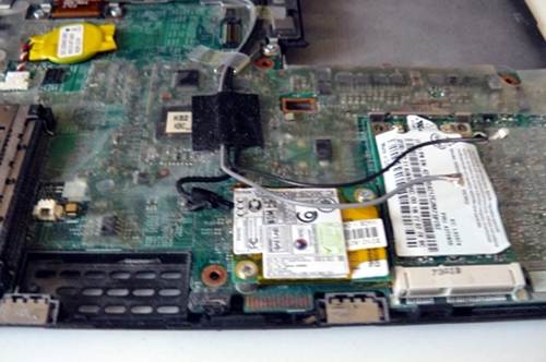
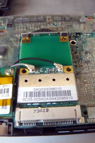
Connect the wifi antenna cables. At the start of the tutorial, this
|
|
|
|
|
system had an Intel wifi chip. Here you see I've replaced it with an
|
|
|
|
|
Atheros AR5B95 (supports 802.11n and can be used without blobs):\
|
|
|
|
|
|
|
|
|
|
|
|
|
|
|
Connect the modem cable:\
|
|
|
|
|
|
|
|
|
|
|
|
|
|
|
Connect the speaker:\
|
|
|
|
|
|
|
|
|
|
|
|
|
|
|
You should now have this:\
|
|
|
|
|
|
|
|
|
|
|
|
|
|
|
Re-connect the upper chassis:\
|
|
|
|
|
|
|
|
|
|
|
|
|
|
|
Re-connect the keyboard:\
|
|
|
|
|
|
|
|
|
|
|
|
|
|
|
Re-insert the screws that you removed earlier:\
|
|
|
|
|
|
|
|
|
|
|
|
|
|
|
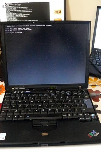
Power on!\
|
|
|
|
|
|
|
|
|
|
|
|
|
|
|
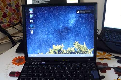
Operating system:\
|
|
|
|
|
|