1103 lines
45 KiB
Markdown
1103 lines
45 KiB
Markdown
---
|
|
title: Read/write 25XX NOR flash via SPI protocol
|
|
x-toc-enable: true
|
|
...
|
|
|
|
Need help?
|
|
==========
|
|
|
|
Help is available on [Libreboot IRC](../../contact.md) and other channels.
|
|
|
|
If you want professional installation, Minifree Ltd sells [Libreboot
|
|
pre-installed](https://minifree.org/) on select hardware, and it also provides
|
|
a [Libreboot preinstall service](https://minifree.org/product/installation-service/)
|
|
if you want to send your machine in to have Libreboot installed for you.
|
|
|
|
Leah Rowe, the founder and lead developer of Libreboot, also owns and
|
|
operates Minifree Ltd; sales provide funding for the Libreboot project.
|
|
|
|
Introduction
|
|
============
|
|
|
|
NOTE: Libreboot standardises on [flashprog](https://flashprog.org/wiki/Flashprog)
|
|
now, as of 27 January 2024, which is a fork of flashrom.
|
|
|
|
**[PLEASE READ THESE INSTRUCTIONS BEFORE INSTALLING](../../news/safety.md),
|
|
OR YOU MIGHT BRICK YOUR MACHINE: [SAFETY PRECAUTIONS](../../news/safety.md)**
|
|
|
|
This guide will teach you how to use various tools for externally reprogramming
|
|
a 25xx NOR flash via SPI protocol. This is the most common type of flash IC for
|
|
computers that coreboot runs on. Almost every system currently supported by
|
|
libreboot uses this type of boot flash; the only exception is ASUS KFSN4-DRE,
|
|
which uses LPC flash in a PLCC32 socket, which you can simply hot-swap after
|
|
booting the vendor firmware, and then flash internally. Simple!
|
|
|
|
We will be using
|
|
the [flashprog](https://flashprog.org/Flashrom) software which is written to
|
|
dump, erase and rewrite these flash chips.
|
|
|
|
libreboot currently documents how to use these SPI programmers:
|
|
|
|
* Raspberry Pi Pico
|
|
* Raspberry Pi (RPi) single-board computers
|
|
* BeagleBone Black (BBB)
|
|
* Libre Computer 'Le Potato'
|
|
|
|
Many other SPI programmers exist. More of them will be documented on this page,
|
|
at a date in the future. You can otherwise figure it out on your own; certain
|
|
parts of this page are still useful, even if you're using a programmer that
|
|
Libreboot does not yet document.
|
|
|
|
Most systems in libreboot have to be re-flashed externally, using instructions
|
|
on this and similar guides, the first time you flash. However, on all currently
|
|
supported systems, it's possible that you can re-flash *internally* when
|
|
libreboot is running.
|
|
|
|
*Internal* flashing means that the host CPU on your system can re-program the
|
|
SPI flash, using an on-board SPI programmer (which all boards have). You do this
|
|
from Linux, with flashprog.
|
|
|
|
*This* guide that you're reading now is for using an *external* programmer. It
|
|
is called *external* because it's not the *internal* one on your mainboard.
|
|
|
|
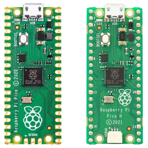
Raspberry Pi Pico
|
|
=================
|
|
|
|
|
|
|
|
If you don't already have a programmer, get this one! It's well engineered,
|
|
safe, and costs just $5 with headers pre-soldered (Raspberry Pi Pico H).
|
|
Additionally, all the software running on it is free, down to the full
|
|
[Boot ROM](https://github.com/raspberrypi/pico-bootrom). The wireless
|
|
versions (Pico W & Pico WH) need vendor firmware to use the Wi-Fi chip,
|
|
but that is not needed for following this guide.
|
|
|
|
A Pico has proper 3.3V logic levels, unlike a ch341a. Which means it won't
|
|
destroy your board by sending 5V to it. If you have a 1.8V flash chip,
|
|
you need to add a logic level converter.
|
|
|
|
First, connect just the Pico to your computer with a micro-USB cable.
|
|
Mount it like any other USB flash drive. If it isn't detected, you might need
|
|
to press the BOOTSEL button while you plug it in (this forces it into the
|
|
bootloader mode).
|
|
|
|
You can download the serprog firmware here:\
|
|
<https://codeberg.org/libreboot/pico-serprog>\
|
|
or here:\
|
|
<https://notabug.org/libreboot/pico-serprog>
|
|
|
|
You can also find the source code for these, under `src/` in Libreboot release
|
|
archives (source code tarball), and/or under `src/` in `lbmk.git` if downloading
|
|
using the build instructions below.
|
|
|
|
Copy the file `rpi-pico-serprog.uf2` into your Pico. To build this firmware, you
|
|
could build it yourself or you could also clone `lbmk.git` and [install build
|
|
dependencies](../build/#first-install-build-dependencies), then inside lbmk,
|
|
do:
|
|
|
|
./build serprog rp2040 pico
|
|
|
|
or for the W version:
|
|
|
|
./build serprog rp2040 pico_w
|
|
|
|
This will automatically build the rpi-pico firmware, and the file will be
|
|
at `bin/serprog_rp2040/serprog_pico.uf2`. This binary will be provided
|
|
pre-compiled in the next Libreboot release, after the 20230625 release.
|
|
|
|
Disconnect the Pico and proceed to wire it to your
|
|
[flash chip](/docs/install/spi.html#identify-which-flash-type-you-have).
|
|
|
|
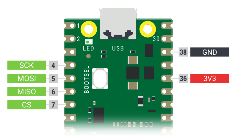
**NOTE: SCK and CLK mean the same thing. The diagram below says SCK, and other
|
|
parts of this guide say CLK. It's the same thing!**
|
|
|
|
|
|
|
|
|
|
|
|
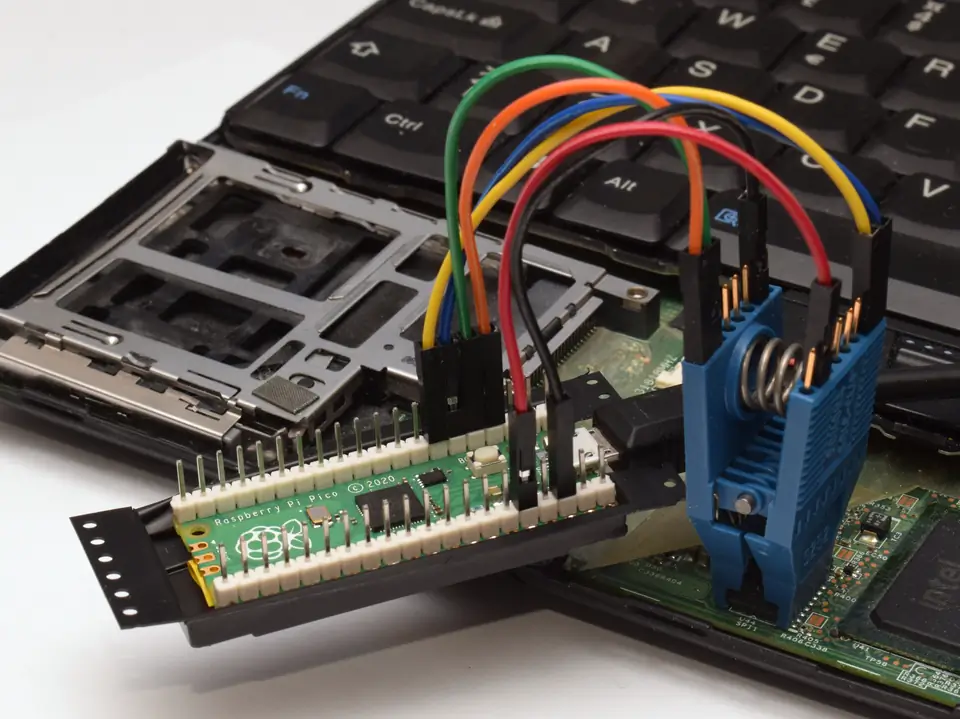
Headers were manually soldered on the top side, and the plastic packaging
|
|
was repurposed as an insulating base. These might be nice to have, but by no
|
|
means necessary. If your headers are on the other side, just keep in mind
|
|
that the pinouts are as seen from above.
|
|
|
|
Now run (as root) `dmesg -wH`. When you plug in the Pico, a line like this
|
|
will appear:
|
|
|
|
[453876.669019] cdc_acm 2-1.2:1.0: ttyACMx: USB ACM device
|
|
|
|
Take note of the ttyACMx. Flashrom is now usable
|
|
(substitute ttyACMx with what you observed earlier).
|
|
|
|
flashprog -p serprog:dev=/dev/ttyACMx,spispeed=16M
|
|
|
|
spispeed=32M usually works, but since it's not much faster it's probably
|
|
not worth it. The 12Mbps USB port is limiting the actual speed here.
|
|
|
|
Do not use CH341A!
|
|
==================
|
|
|
|
NOR flashes on libreboot systems run on 3.3V DC or 1.8V DC, and this includes
|
|
data lines. CH341A has 5V logic levels on data lines, which will damage your
|
|
SPI flash and also the southbridge that it's connected to, plus anything else
|
|
that it's connected to.
|
|
|
|
These ch341a programmers are unfortunately very popular. DO NOT use it unless
|
|
you have fixed the issue. You CAN fix it so that the data lines are 3.3v, if
|
|
you follow the notes here:
|
|
|
|
<https://www.eevblog.com/forum/repair/ch341a-serial-memory-programmer-power-supply-fix/>
|
|
|
|
In practise, most people will not fix their ch341a and instead just risk it,
|
|
so no documentation will be provided for ch341a on this website. It is best
|
|
to discourage use of that device.
|
|
|
|
**Not covered on that eevblog page: the WP/HOLD pins (pins 3 and 7) must be
|
|
held high via pull-up resistors, but on CH341A dongles, they are directly
|
|
connected to 3.3V DC (continuity with pin 8). It is advisable to cut these
|
|
two connections, to the WP and HOLD pins, and jump the cuts using pull-up
|
|
resistors instead. A value between 1k to 10k (ohms) should be fine.**
|
|
|
|
**In the event of a surge, like for example you connect the clip wrongly and
|
|
cause a short circuit between two pins, lack of pull-up resistors on WP/HOLD
|
|
could cause a direct short between VCC/ground, which would cause a lot of heat
|
|
build up and possibly fire (and definitely damaged circuitry). On SOIC8, pin 3
|
|
is WP and 4 is GND, so a direct 3.3v connection there is quite hazardous for
|
|
that reason; all the more reason to use a pull-up resistor.**
|
|
|
|
The mainboard that you want to flash (if using e.g. pomona clip) will probably
|
|
have pull-up resistors on it already for WP/HOLD, so simply cutting WP/HOLD
|
|
on the CH341A would also be acceptable. The pull-up resistors that you
|
|
place (in such a mod) on the CH341A are only useful if you also want to flash
|
|
chips in the ZIF socket. If pull-up resistors exist both on e.g. the laptop
|
|
mainboard and on the CH341A, it just means the equivalent series resistance
|
|
will be of the two resistors (on each line) in parallel. If we assume that
|
|
a laptop is likely to have a resistor size of ~3.3k for pull-ups, then a value
|
|
of ~5.6k ohms on the CH341A side seems reasonable.
|
|
|
|
Alternatively, you might work around the voltage issue by using an adapter with
|
|
logic-level converter, making sure to have matching vcc going into the flash.
|
|
Use of a logic level converter would be quite flexible, in this scenario, and
|
|
you could use it to set many voltages such as 1.8v or 3.3v.
|
|
|
|
In case it's not clear:
|
|
|
|
**Please do not buy the ch341a!** It is incorrectly engineered for the purpose
|
|
of ROM flashing on systems with 3.3v SPI (which is most coreboot systems). DO
|
|
NOT USE IT! This issue still isn't fixed by the manufacturer, and it doesn't
|
|
look like they will ever fix it.
|
|
|
|
If you see someone talking about CH341A, please direct them to this page and
|
|
tell them why the CH341A is bad.
|
|
|
|
These photos show both modifications (3.3v logic and WP/HOLD pull-up
|
|
resistors) performed, on the black CH341A:\
|
|
<img tabindex=1 src="https://av.libreboot.org/ch341a/0000_th.jpg" /><span class="f"><img src="https://av.libreboot.org/ch341a/0000.jpg" /></span>
|
|
<img tabindex=1 src="https://av.libreboot.org/ch341a/0001_th.jpg" /><span class="f"><img src="https://av.libreboot.org/ch341a/0001.jpg" /></span>
|
|
|
|
The green version (not shown above) may come with 3.3v logic already wired, but
|
|
still needs to have pull-up resistors placed for WP/HOLD.
|
|
|
|
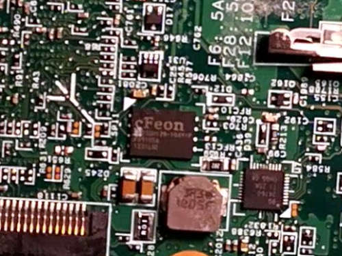
Identify which flash type you have
|
|
==================================
|
|
|
|
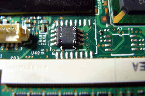
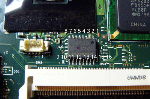
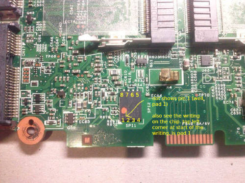
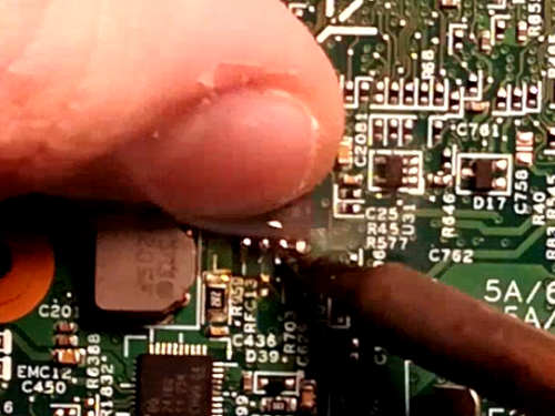
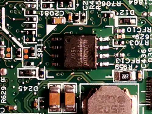
In all of them, a dot or marking shows pin 1 (in the case of WSON8, pad 1).
|
|
|
|
Use the following photos and then look at your board. When you've figured out
|
|
what type of chip you have, use that knowledge and the rest of this guide, to
|
|
accomplish your goal, which is to read from and/or write to the boot flash.
|
|
|
|
SOIC8
|
|
-----
|
|
|
|
|
|
|
|
| Pin | Function |
|
|
|-----|----------|
|
|
| 1 | CS |
|
|
| 2 | MISO |
|
|
| 3 | WP |
|
|
| 4 | GND |
|
|
| 5 | MOSI |
|
|
| 6 | CLK |
|
|
| 7 | HOLD |
|
|
| 8 | VCC |
|
|
|
|
SOIC16
|
|
------
|
|
|
|
|
|
|
|
| Pin | Function |
|
|
|-----|----------|
|
|
| 1 | HOLD |
|
|
| 2 | VCC |
|
|
| 7 | CS |
|
|
| 8 | MISO |
|
|
| 9 | WP |
|
|
| 10 | GND |
|
|
| 15 | MOSI |
|
|
| 16 | CLK |
|
|
|
|
SOIC8 and SOIC16 are the most common types, but there are others:
|
|
|
|
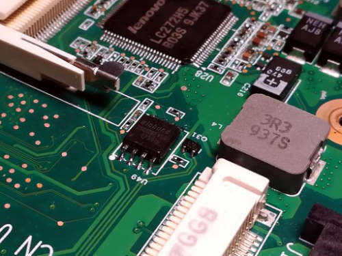
WSON8
|
|
-----
|
|
|
|
It will be like this on an X200S or X200 Tablet:\
|
|
|
|
|
|
Pinout is the same as SOIC8 above.
|
|
|
|
On T400S, it is in this location near the RAM:\
|
|
\
|
|
NOTE: in this photo, the chip has been replaced with SOIC8.
|
|
|
|
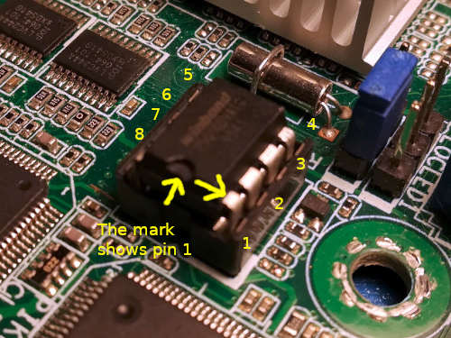
DIP8
|
|
----
|
|
|
|
|
|
|
|
Pinout is the same as SOIC8 above.
|
|
|
|
Supply Voltage
|
|
--------------
|
|
|
|
Historically, all boards that Libreboot supports happened to have SPI NOR chips
|
|
which work at 3.3V DC. With the recent addition of Chromebooks whose chips are
|
|
rated for 1.8V DC, this can no longer be assumed.
|
|
|
|
Inspect the chip on your board for a part number, look up the datasheet for it.
|
|
Find out and make note of the power supply voltage it needs. If it doesn't
|
|
match the voltage output by your external flashing hardware, you should only
|
|
connect it to the chip through an adapter or logic level converter, never
|
|
directly.
|
|
|
|
Software configuration
|
|
======================
|
|
|
|
General/Le potato
|
|
-----------------
|
|
|
|
The [generic guide](spi_generic.md) is intended to help those looking to use an
|
|
SBC which is not listed in this guide.
|
|
The guide will, however, use the libre computer 'Le Potato' as a reference board.
|
|
If you have that board, you should refer to the [generic guide.](spi_generic.md)
|
|
|
|
BeagleBone Black (BBB)
|
|
----------------------
|
|
|
|
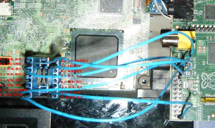
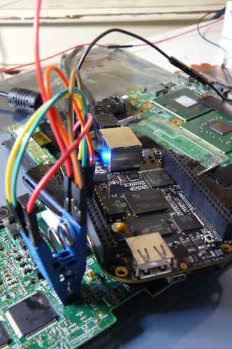
SSH into your BeagleBone Black. It is assumed that you are running Debian 9 on
|
|
your BBB. You will run `flashprog` from your BBB.
|
|
|
|
NOTE: This section is out of date, because it is written for Debian 9 (running
|
|
on the BBB)
|
|
|
|
Run the following commands as root to enable spidev:
|
|
|
|
```
|
|
config-pin P9.17 spi_cs
|
|
config-pin P9.18 spi
|
|
config-pin P9.21 spi
|
|
config-pin P9.22 spi_sclk
|
|
```
|
|
|
|
Verify that the spidev devices now exist:
|
|
|
|
ls /dev/spidev*
|
|
|
|
Output:
|
|
|
|
/dev/spidev1.0 /dev/spidev1.1 /dev/spidev2.0 /dev/spidev2.1
|
|
|
|
Now the BBB is ready to be used for flashing. The following systemd service
|
|
file can optionally be enabled to make this persistent across reboots.
|
|
|
|
```
|
|
[Unit]
|
|
Description=Enable SPI function on pins
|
|
|
|
[Service]
|
|
Type=oneshot
|
|
ExecStart=config-pin P9.17 spi_cs
|
|
ExecStart=config-pin P9.18 spi
|
|
ExecStart=config-pin P9.21 spi
|
|
ExecStart=config-pin P9.22 spi_sclk
|
|
RemainAfterExit=yes
|
|
|
|
[Install]
|
|
WantedBy=multi-user.target
|
|
```
|
|
|
|
Now test flashprog:
|
|
|
|
./flashprog -p linux_spi:dev=/dev/spidev1.0,spispeed=512
|
|
|
|
It is important to use `spispeed=512` or a lower number such as 256 or 128,
|
|
because otherwise the BBB will be quite unstable.
|
|
|
|
Example output:
|
|
|
|
```
|
|
Calibrating delay loop... OK.
|
|
No EEPROM/flash device found.
|
|
Note: flashprog can never write if the flash chip isn't found automatically.
|
|
```
|
|
|
|
This means that it's working (the clip isn't connected to any flash
|
|
chip, so the error is fine).
|
|
|
|
Caution about BBB
|
|
-----------------
|
|
|
|
BeagleBone Black is not recommended, because it's very slow and unstable for
|
|
SPI flashing, and nowadays much better options exist. We used to mainly
|
|
recommend the BBB, because of the fact that it can be used with entirely Free
|
|
Software on it, but nowadays there are superior options.
|
|
|
|
TODO: document other SPI flashers
|
|
|
|
Rasberry Pi (RPi)
|
|
-----------------
|
|
|
|
SSH into your Raspberry Pi. You will run `flashprog` from your Raspberry Pi.
|
|
|
|
You must configure `spidev` on your Raspberry Pi. This is a special driver in
|
|
the Linux kernel; technically, the driver name is `spi-bcm2835`.
|
|
|
|
This page has info:\
|
|
<https://www.raspberrypi.org/documentation/hardware/raspberrypi/spi/README.md>
|
|
|
|
In your Raspberry Pi, which we assume you're running the latest Raspbian version
|
|
on, do this:
|
|
|
|
sudo raspi-config
|
|
|
|
Under the Interface section, you can enable SPI.
|
|
|
|
The device for communicating via SPI as at `/dev/spidev0.0`
|
|
|
|
RPi Drive Strength
|
|
------------------
|
|
Flashrom on the RPi may not be able to detect the SPI flash chip on some
|
|
systems, even if your wiring and clip are set up perfectly. This may be due to
|
|
the drive strength of the Raspberry Pi GPIOs, which is 8mA by default. Drive
|
|
strength is essentially the maximum current the pin can output while also
|
|
maintaining the minimum high-level voltage. In the case of the Pi, this voltage
|
|
is 3.0V.
|
|
|
|
Similarly, the SPI flash chip has a minimum voltage it will accept as a high
|
|
logic value. This is commonly 0.7\*VCC for SPI flash, which is 2.31V for 3.3V
|
|
chips. If the drive strength is too low, the voltage at the pins of the flash
|
|
chip may fall below this minimum voltage, causing it to register as a low logic
|
|
value instead of the high value that was sent.
|
|
|
|
On many systems, the VCC pin of the SPI flash is shared with other chips on the
|
|
system, causing them to be powered through the voltage supplied through your
|
|
programming clip. In this case, parts of the chipset may power up, and it may
|
|
attempt to set the SPI lines high or low, interfering with the data the Pi is
|
|
trying to send. If the Pi and chipset are trying to set a pin to different
|
|
values, the side with a greater drive strength will be able to "pull" the
|
|
voltage toward the level it wants to set.
|
|
|
|
Fortunately, the drive strength of the Raspberry Pi can be increased up to
|
|
16mA. There are a few tools that can set this, such as the pigs utility from
|
|
the pigpio project. On the Raspberry Pi OS, the following commands should
|
|
install pigpio and set the drive strength to 16mA:
|
|
|
|
Install pigpio:
|
|
|
|
sudo apt install pigpio
|
|
|
|
Start the pigpiod daemon, which the pigs utility communicates with to interact
|
|
with the gpios:
|
|
|
|
sudo pigpiod
|
|
|
|
Set the drive strength of GPIO group 0, which contains the spi0 pins, to 16mA:
|
|
|
|
pigs pads 0 16
|
|
|
|
Note that the drive strength hardware works in multiples of 2mA, and pigs will
|
|
round odd values up to the next multiple of 2. You can check the current drive
|
|
strength using
|
|
|
|
pigs padg 0
|
|
|
|
WARNING: If the chipset is very strongly trying to drive a pin to a value
|
|
opposite that of the Pi, more than 16mA pass through the Pi's GPIO pins, which
|
|
may damage them as they are only designed for 16mA. The drive strength is NOT a
|
|
current limit. That said, this is a risk to the Pi regardless of the drive
|
|
strength. Resistors between the chipset and the flash should protect against
|
|
this, though not all boards have these.
|
|
|
|
See
|
|
<https://www.raspberrypi.com/documentation/computers/raspberry-pi.html#gpio-pads-control>
|
|
for more information about the drive strength control on the Pi.
|
|
|
|
Caution about RPi
|
|
-----------------
|
|
|
|
Basically, the Raspbian project, now called Raspberry Pi OS, put in their repo
|
|
an update that added a new "trusted" repository, which just so happened to be
|
|
a Microsoft software repository. They seem to have done this for VS Code, but
|
|
the problem here is that it gave Microsoft free reign to define whatever
|
|
dependencies they liked (as per apt-get rules), and every time you updated,
|
|
you would be pinging Microsoft servers. Do you think that is strange?
|
|
|
|
Microsoft shouldn't have *any* access to your Linux system! This was the
|
|
commit that Raspbian added to their distro, which added this what should rightly
|
|
be called a security vulnerability, intentionally:
|
|
|
|
* <https://github.com/RPi-Distro/raspberrypi-sys-mods/commit/655cad5aee6457b94fc2336b1ff3c1104ccb4351>
|
|
|
|
They then removed it, after a public backlash, via the following commits:
|
|
|
|
* <https://github.com/RPi-Distro/raspberrypi-sys-mods/commit/ed96790e6de281bc393b575c38aa8071ce39b555>
|
|
* <https://github.com/RPi-Distro/raspberrypi-sys-mods/commit/4d1afece91008f3787495b520ac03b53fef754c6>
|
|
|
|
Libre firmware on RPi
|
|
---------------------
|
|
|
|
The boot firmware on older Raspberry Pi models can be replaced, with entirely
|
|
libre firmware. This may be a useful additional step, for some users. See:
|
|
|
|
<https://github.com/librerpi/>
|
|
|
|
Website:
|
|
|
|
<https://librerpi.github.io/>
|
|
|
|
Install flashprog
|
|
----------------
|
|
|
|
If you're using a BBB or RPi, you will do this while SSH'd into those.
|
|
|
|
Flashrom is the software that you will use, for dumping, erasing and rewriting
|
|
the contents of your NOR flash.
|
|
|
|
In the libreboot build system, from the Git repository, you can download and
|
|
install flashprog. Do this after downloading the
|
|
[lbmk Git repository](https://codeberg.org/libreboot/lbmk):
|
|
|
|
cd lbmk
|
|
sudo ./build dependencies ubuntu2004
|
|
|
|
NOTE: debian, arch or void can be written instead of ubuntu2004. the debian
|
|
script is also applicable to newer ubuntu versions
|
|
|
|
./update trees -b flashprog
|
|
|
|
If the `ubuntu2004` script complains about missing dependencies, just modify
|
|
the dependencies config to remove those dependencies. The script is located
|
|
at `config/dependencies/ubuntu2004` and it is written for
|
|
Ubuntu 20.04, but it should work fine in other Linux distributions that use
|
|
the `apt-get` package manager.
|
|
|
|
A `flashprog/` directory will be present, with a `flashprog` executable inside
|
|
of it. If you got an error about missing package when running the dependencies
|
|
command above, tweak `config/dependencies/ubuntu2004`. That
|
|
script downloads and installs build dependencies in apt-get and it is intended
|
|
for use on x86-64 systems running Ubuntu 20.04, but it should work in Raspbian
|
|
on the Raspberry Pi.
|
|
|
|
Alternatively, you may download flashprog directly from upstream
|
|
at <https://flashprog.org/Flashrom>
|
|
|
|
If you're flashing a Macronix flashchip on a ThinkPad X200, you will want to
|
|
use a special patched version of flashprog, which you can download here:
|
|
<https://vimuser.org/hackrom.tar.xz> - patched source code is available, and a
|
|
binary is also available that you can simply run. Pass the `--workaround-mx`
|
|
argument in flashprog. This mitigates stability issues.
|
|
|
|
If you downloaded the flashprog source code directly, you can go into the
|
|
directory and simply type `make`. In the libreboot build system, build
|
|
dependencies are documented in configuration files located
|
|
at `config/dependencies/` which you can install
|
|
using the `apt-get` software.
|
|
|
|
How to use flashprog
|
|
===================
|
|
|
|
Read past these sections, further down this page, to learn about specific chip
|
|
types and how to wire them.
|
|
|
|
Reading
|
|
-------
|
|
|
|
Before flashing a new ROM image, it is highly advisable that you dump the
|
|
current chip contents to a file.
|
|
|
|
Run this command to see if 25xx flash is detected, with your RPi properly
|
|
wired.
|
|
|
|
sudo ./flashprog -p linux_spi:dev=/dev/spidev0.0,spispeed=32768
|
|
|
|
For BBB, you must use a lower speed and a different device path:
|
|
|
|
sudo ./flashprog -p linux_spi:dev=/dev/spidev1.0,spispeed=512
|
|
|
|
On BBB, never use a speed higher than `spispeed=512`. In some cases, you may
|
|
even need to go as low as `spispeed=128`. The BBB is highly unstable and
|
|
unreliable for SPI flashing. When you're reading, take multiple dumps and
|
|
verify that the checksums match, before you flash. You may have to flash your
|
|
chip several times!
|
|
|
|
NOTE: On some systems, higher speeds will be unstable. On those systems, try
|
|
lower speed like `spispeed=4096` or even `spispeed=2048` which should, in most
|
|
cases, work just fine but it will obviously be slower. The `spispeed=32768`
|
|
setting works just fine on most setups if you use short wires, within 10cm.
|
|
|
|
If flash chip is detected you may try reading (dumping) the flash contents now,
|
|
or you can try flashing it with a new ROM.
|
|
|
|
Dump it like so (RPi):
|
|
|
|
sudo ./flashprog -p linux_spi:dev=/dev/spidev0.0,spispeed=32768 -r dump.bin
|
|
|
|
For BBB, do this:
|
|
|
|
sudo ./flashprog -p linux_spi:dev=/dev/spidev1.0,spispeed=512 -r dump.bin
|
|
|
|
It is advisable to take a *2nd* dump, e.g. `dump2.bin`, and then check sha1sum:
|
|
|
|
sha1sum dump*.bin
|
|
|
|
If the checksums match, it indicates that you have a good dump. If they do not,
|
|
check your wiring. Wires should be within 10cm length for best stability, and
|
|
they should all be the same length (VCC and GND wires can be longer).
|
|
|
|
This advice is *especially* applicable to the BBB, which is highly unreliable.
|
|
|
|
For boards with more than one flash chip you will need to read from both chips
|
|
and combine them into a single file.
|
|
Most of the time, a two chip setup includes one 8mb 'bottom' chip and one 4mb
|
|
'top' chip.
|
|
The setup just described applies to the x230, t430, t530, and t440p.
|
|
For other boards, make sure you know which chip contains the lower and upper
|
|
portions of the rom.
|
|
You can combine both flashes together with `cat` for example:
|
|
|
|
cat bottom_8mb.rom top_4mb.rom > full_12mb.rom
|
|
|
|
Note that you will need this combined rom if you intend to manually extract vendor
|
|
files, which is a method not officially supported by Libreboot's build system.
|
|
|
|
Writing
|
|
-------
|
|
|
|
Next, run this command (RPi):
|
|
|
|
sudo ./flashprog -p linux_spi:dev=/dev/spidev0.0,spispeed=32768 -w /path/to/libreboot.rom
|
|
|
|
If using BBB:
|
|
|
|
sudo ./flashprog -p linux_spi:dev=/dev/spidev1.0,spispeed=512 -w /path/to/libreboot.rom
|
|
|
|
If using BBB, you may have to use a lower speed than 512. You may also have to
|
|
re-flash several times before it works fully.
|
|
|
|
Again, use a lower `spispeed` value if you need to, for stability.
|
|
|
|
Once that command outputs the following, the flash has completed
|
|
successfully. If not, just flash again.
|
|
|
|
```
|
|
Reading old flash chip contents... done.
|
|
Erasing and writing flash chip... Erase/write done.
|
|
Verifying flash... VERIFIED.
|
|
```
|
|
|
|
If it says "VERIFIED" or says that the chip contents are identical to the
|
|
requested image, then the chip is properly flashed.
|
|
|
|
If the board you are writing to has two chips you'll need to split the rom into
|
|
two sections.
|
|
For example, to split a rom for the x230, t430, t530, or t440p run:
|
|
|
|
dd if=libreboot_12mb.rom bs=1M of=bottom.rom count=8
|
|
dd if=libreboot_12mb.rom bs=1M of=top.rom skip=8
|
|
|
|
Flash the resulting roms to each of their respective chips according to the above instructions.
|
|
|
|
|
|
Hardware configuration
|
|
======================
|
|
|
|
Refer to the above guidance about software configuration. The following advice
|
|
will teach you how to wire each type of flash chip.
|
|
|
|
WARNINGS
|
|
--------
|
|
|
|
Do not connect the power source until your chip is otherwise properly
|
|
wired. For instance, do not connect a test clip that has power attached.
|
|
|
|
Do not *disconnect* your chip from the flasher until you've disconnected or
|
|
turned off the power source.
|
|
|
|
BE CAREFUL that you are indeed supplying the appropriate supply voltage to the
|
|
chip. SPI flashes on most of the currently supported libreboot hardware run on
|
|
3.3V DC and logic at that level too. Some of them (at least Chromebooks) can
|
|
have chips that run on 1.8V DC. You should make sure to check the part number
|
|
and datasheet of the SPI flash chip for the supply voltage it requires. If your
|
|
external flashing hardware doesn't match it, use an adapter or logic level
|
|
converter to flash.
|
|
|
|
It is important to CHECK that you are running on the correct voltage, when you
|
|
do anything with these chips. Lower than the rated supply voltage won't damage
|
|
anything, but higher will fry your chip (on most 3.3V chips, the tolerated
|
|
voltage range is between 2.7V and 3.6V, but 3.3V is the most ideal level).
|
|
|
|
DO NOT connect more than 1 DC power source to your flash chip either!
|
|
Mixing voltages like that can easily cause damage to your equipment, and to
|
|
your chip/mainboard.
|
|
|
|
MISO/MOSI/CS/CLK lines
|
|
----------------------
|
|
|
|
You may want to add 47ohm series resistors on these lines, when flashing the
|
|
chips. Only do it on those lines (NOT the VCC or GND lines). This provides
|
|
some protection from over-current. On Intel platforms, the SPI flash is usually
|
|
connected via such resistors, directly to the Southbridge chipset.
|
|
|
|
ISP programming and VCC diode
|
|
-----------------------------
|
|
|
|
ISP means in-system programming. It's when you flash a chip that is already
|
|
mounted to the mainboard of your computer that you wish to install libreboot
|
|
on.
|
|
|
|
It may be beneficial to modify the mainboard so that the SPI flash is powered
|
|
(on the VCC pin) through a diode, but please note: a diode will cause a voltage
|
|
drop. The tolerated range for a chip expecting 3.3V VCC is usually around 2.7V
|
|
to 3.6V DC, and the drop may cause the voltage to fall outside that. If you do
|
|
this, please also ensure that the WP and HOLD pins are still held to a high
|
|
logic state; each via their own resistor (1K to 10K ohms) connected to the
|
|
*same* power source going through the diode.
|
|
|
|
The reason is simple: on most systems, the flash shares a common power rail
|
|
with many other components on the board, which draw a lot of current. Further,
|
|
if you accidentally provide too much voltage or cause an overcurrent, you could
|
|
fry those other components but if there is diode protection, you'll only fry
|
|
the boot flash (and it is very easy to replace, if you have good soldering
|
|
skills).
|
|
|
|
When you've placed the diode, ensure that VCC on the chip is isolated from all
|
|
other components on that board, which share the same power rail. Further,
|
|
ensure that the pull-up resistors for WP/HOLD are *only* connected to the side
|
|
of the diode that has continuity with the VCC pin (this is important because if
|
|
they're not, they won't be held high while doing ISP flashing, even if they're
|
|
still held high when the mainboard is fully powered on).
|
|
|
|
Furthermore: ensure that the SPI flash is operating at the appropriate supply
|
|
voltage (2.7V to 3.6V for a 3.3V chip) when fully powered on, after installing
|
|
the diode.
|
|
|
|
If it's a desktop/workstation/server board (not a laptop), you could de-solder
|
|
the SOIC8/WSON8 if it uses that, and replace with an IC socket (for SOIC8,
|
|
WSON8 or DIP8, whatever you want), because then you could easily just insert
|
|
the flash into a breadboard when flashing.
|
|
|
|
TODO: Make a page on libreboot.org, showing how to do this on all mainboards
|
|
supported by libreboot.
|
|
|
|
GPIO pins on BeagleBone Black (BBB)
|
|
-----------------------------------
|
|
|
|
Use this image for reference when connecting the pomona to the BBB:
|
|
<https://beagleboard.org/Support/bone101#headers> (D0 = MISO or connects
|
|
to MISO).
|
|
|
|
On that page, look at the *P9 header*. It is what you will use to wire up your
|
|
chip for flashing.
|
|
|
|
GPIO pins on Raspberry Pi (RPi) 40 Pin
|
|
--------------------------------------
|
|
|
|
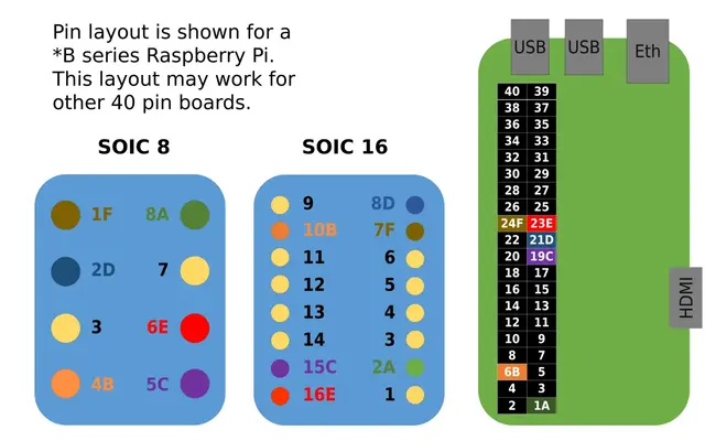
This diagram shows the pinout for most modern Pi's and Pi derivatives.
|
|
The diagram shows the pins of an RPi on the left and the two SOIC clips
|
|
on the left.
|
|
|
|
|
|
|
|
GPIO pins on Raspberry Pi (RPi) 26 Pin
|
|
-------------------------------
|
|
|
|
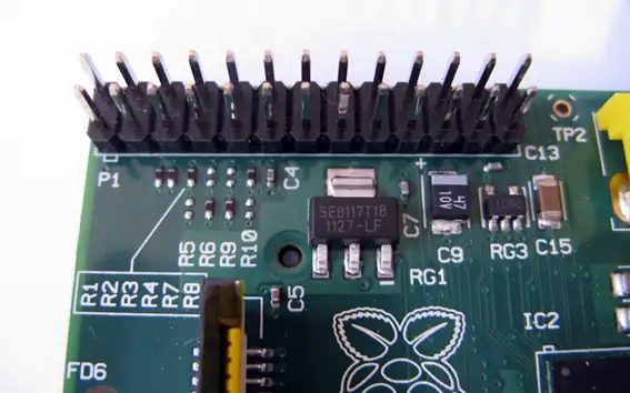
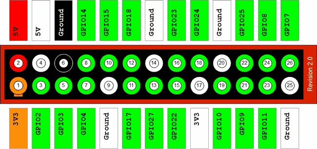
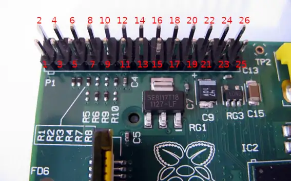
Diagram of the 26 GPIO Pins of the Raspberry Pi Model B (for the Model
|
|
B+ with 40 pins, start counting from the right and leave 14 pins):
|
|
|
|
|
|
|
|
Use this as a reference for the other sections in this page, seen below:
|
|
|
|
SOIC8/DIP8/WSON8 wiring diagram
|
|
-------------------------------
|
|
|
|
Refer to this diagram:
|
|
|
|
Pin \# 25xx signal RPi(GPIO) BBB(P9 header)
|
|
------ ----------- ---------- --------------
|
|
1 CS 24 17
|
|
2 MISO 21 21
|
|
3 *not used* *not used* *not used*
|
|
4 GND 25 1
|
|
5 MOSI 19 18
|
|
6 CLK 23 22
|
|
7 *not used* *not used* *not used*
|
|
8 VCC 1 3
|
|
|
|
On your SOIC8, there will be a dot in one of the corners. The dot is pin 1.
|
|
|
|
NOTE: pins 3 and 7 are WP/HOLD pins. If flashing a chip on a breadboard, please
|
|
use pull-up resistors on those (see notes below), and decoupling capacitor on
|
|
pin 8 (VCC).
|
|
|
|
NOTE: On X60/T60 thinkpads, don't connect pin 8. Instead, plug in your the PSU
|
|
to the charging port on your mainboard, but do not power on the mainboard. This
|
|
will provide a stable 3.3V voltage, with adequate current levels. On those
|
|
laptops, this is necessary because the flash shares a common 3.3V DC rail with
|
|
many other ICs that all draw quite a lot of current.
|
|
|
|
SOIC16 wiring diagram (Raspberry Pi)
|
|
------------------------------------
|
|
|
|
RPi GPIO header:\
|
|
|
|

|
|
|
|
BBB P9 header:\
|
|
<https://beagleboard.org/static/images/cape-headers.png>
|
|
|
|
Refer to this diagram:
|
|
|
|
Pin \# 25xx signal RPi(GPIO) BBB(P9 header)
|
|
-------- -------------- ----------- --------------
|
|
1 *not used* *not used* *not used*
|
|
2 VCC 1 3
|
|
3 *not used* *not used* *not used*
|
|
4 *not used* *not used* *not used*
|
|
5 *not used* *not used* *not used*
|
|
6 *not used* *not used* *not used*
|
|
7 CS\# 24 17
|
|
8 MISO 21 21
|
|
9 *not used* *not used* *not used*
|
|
10 GND 25 1
|
|
11 *not used* *not used* *not used*
|
|
12 *not used* *not used* *not used*
|
|
13 *not used* *not used* *not used*
|
|
14 *not used* *not used* *not used*
|
|
15 MOSI 19 18
|
|
16 SCLK 23 22
|
|
|
|
Refer to the RPi GPIO guide above, on this page.
|
|
|
|
On your SOIC16, there will be a dot in one of the corners. The dot is pin 1.
|
|
|
|
NOTE: pins 1 and 9 are WP/HOLD pins. If flashing a chip on a breadboard, please
|
|
use pull-up resistors on those (see notes below), and decoupling capacitor on
|
|
pin 2 (VCC).
|
|
|
|
Pull-up resistors and decoupling capacitors
|
|
-------------------------------------------
|
|
|
|
**Do this for chips mounted to a breadboard. Ignore this section if you're
|
|
flashing a chip that is already soldered to a mainboard.**
|
|
|
|
This section is only relevant if you're flashing a new chip that is not yet
|
|
mounted to a mainboard. You need pull-up resistors on the WP and HOLD pins,
|
|
and decoupling capacitors on the VCC pin. If the chip is already mounted to a
|
|
board, whether soldered or in a socket, these capacitors and resistors will
|
|
probably already exist on the board and you can just flash it without pulling
|
|
WP/HOLD high, and without capacitors(just connect your external power source).
|
|
|
|
The best way is as follows:
|
|
|
|
* Insert the DIP8 IC into a breadboard (2.54mm holes), if it's DIP8
|
|
* Insert WSON8 into a WSON8 socket and put on a breadboard, if WSON8
|
|
* Insert SOIC8 into a SOIC8 socket and put on a broadboard, if SOIN8
|
|
* Wire an SPI flasher, using 2.54mm dupont leads, to the breadboard, using
|
|
the correct wiring (see link to SPI flashing guides below)
|
|
|
|
SOIC8/WSON8/DIP8: pin 3 and 7 must be held to a high logic state, which means
|
|
that each pin has its own pull-up resistor to VCC (from the voltage plane that
|
|
pin 8 connects to); anything from 1Kohm to 10Kohm will do. When you're flashing
|
|
a chip that's already on a laptop/desktop/server mainboard, pin 3 and 7 are
|
|
likely already held high, so you don't need to bother.
|
|
|
|
SOIC8/WSON8/DIP8: pin 8, which is VCC, will already have decoupling capacitors on it
|
|
if the chip is on a mainboard, but lone chip flashing means that these capacitors
|
|
do not exist. A capacitor passes AC but blocks DC. Due to electromagnetic
|
|
indunctance, and RF noise from high-speed switching ICs, a DC voltage line isn't
|
|
actually straight (when viewed on an oscilloscope), but actually has low voltage
|
|
AC mixed in; on a particularly noisy line under high load, noise of around 300mV
|
|
or more is common. To smooth out that noise, you wire capacitors from the DC
|
|
line to ground, with the side of the capacitor on VCC as close to the IC's VCC
|
|
pin as possible. We recommend that you use ceramic capacitors for this purpose.
|
|
The recommended capacitors for this are: 100nF and 4.7uF ceramic capacitors.
|
|
Electrolytic capacitors are inferior for this, because they have higher ESR
|
|
(ceramic capacitors have super low ESR, which is very good for decoupling).
|
|
|
|
The result of using a decoupling capacitor is that some of the noise on the DC
|
|
line is filtered to ground, making the DC signal much cleaner/straighter (when
|
|
seen on an oscilloscope).
|
|
|
|
SOIC16: same as above, but use a SOIC16 socked on a breadboard. On SOIC16,
|
|
WP/HOLD are not pin 3/7 like above, but instead pins 1 and 9, so wire your
|
|
pull-up resistors on those. VCC on SOIC16 is pin 2, so wire your decoupling
|
|
capacitors up on that.
|
|
|
|
SOIC8/WSON8/DIP8/SOIC16 not mounted to a mainboard
|
|
--------------------------------------------------
|
|
|
|
If your system has lower capacity SPI flash, you can upgrade. On *most* systems,
|
|
SPI flash is memory mapped and the maximum (in practise) that you can use is a
|
|
16MiB chip. For example, KGPE-D16 and KCMA-D8 mainboards in libreboot have
|
|
2MiB flash by default, but you can easily upgrade these. Another example is the
|
|
ThinkPad X200S, X200 Tablet and T400S, all of which have WSON8 where the best
|
|
course of action is to replace it with a SOIC8 flash chip.
|
|
|
|
In all such cases, flashing a new chip should be done using a breadboard, not
|
|
a test clip. You will use 2.54mm dupont leads to connect your Raspberry Pi.
|
|
For data lines, make sure that all wires are the same length, and about 10cm
|
|
in length (don't use longer lengths than this).
|
|
|
|
Some advice:
|
|
|
|
* DIP8: Strong choice is Winbond W25Q128FVIQ. It is a direct drop-in replacement
|
|
* SOIC8 is possible: Winbond W25Q128FVSIG is a strong choice.
|
|
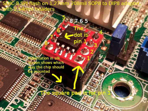
* DIP8 using adapter and SOIC8 is also possible. Use a 208-mil 1.27mm SOP8/SOIC8
|
|
to DIP8 adapter PCB with a
|
|
2.54mm 4-pin header on each side (square pins), then you can slot that in as
|
|
though it were a normal P-DIP 8 IC. This page shows a perfect example:
|
|
<https://coolcomponents.co.uk/products/soic-to-dip-adapter-8-pin>
|
|
* The above SOP8/DIP8 adapter is actually what we recommend, if you're going
|
|
that route. It's made by Sparkfun and widely available; you don't have to buy
|
|
from that particular website. The part number is: BOB-13655
|
|
* If you use a SOP/DIP adapter with a SOIC8 IC, you'll have to solder it
|
|
obviously. K tip is a nice choice for soldering ICs like these. Use good
|
|
flux and 60/40 leaded solder (or 63/37), none of that Rohs lead-free crap.
|
|
|
|
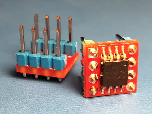
If you go for a SOIC8, mounted it to the SOP to DIP adapter (208mil 1.27mm one)
|
|
and solder 2.54mm headers to it. You could put the 2.54mm pins in a breadboard,
|
|
then solder the chip to the adapter PCB and mount that to the pins on the
|
|
breadboard, to keep it aligned, and solder that. Whith the PCB on the pins, and
|
|
the pins in the breadboard, push the pins inwards a little bit.
|
|
|
|
This is for a new SOIC8 chip, but you can get sockets similar to the one in the
|
|
video, but for WSON8. Sometimes they are called DFN8 or QFN8 sockets. Get one
|
|
that is 1.27mm pitch.
|
|
|
|
If you're flashing/dumping a lone WSON8, get a WSON8/QFN8/DFN8 socket (1.27mm
|
|
pitch) and mount it to a breadboard for flashing. If your mainboard's landing
|
|
pads for the flash IC can take a SOIC8, we recommend that you use a SOIC8
|
|
instead because a test clip is possible later on when you wish to re-flash it,
|
|
however you may be dealing with a board where replacing existing WSON8 with
|
|
SOIC8 is desirable; in that case, you might still want to dump the contents of
|
|
the original WSON8.
|
|
|
|
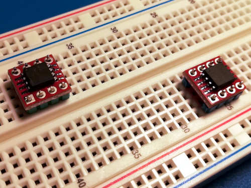
Here is a SOIC8 in a socket, mounted to a breadboard, for flashing:\
|
|
|
|
|
|
Here is a photo of a DIP8 IC:\
|
|

|
|
|
|
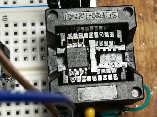
Here is a photo of a SOIC8 in 1.27mm 208mil SOP to DIP adapter:\
|
|
|
|
|
|
NOTE: DIP8 and WSON8-in-socket, and SOIC16-in-socket, are basically the same,
|
|
just adapt accordingly.
|
|
|
|
If you're replacing a DIP8 but using SOIC8 on an adapter, solder it to the
|
|
adapter first, then insert 2.54mm headers (square pins) into a breadboard to
|
|
keep them aligned. Put the SOIC8 on the PCB, onto the pins, and push the pins
|
|
inwards a little bit, and solder that. Alternatively to the breadboard, you
|
|
can just put the 2.54mm pins directly in the DIP8 socket and mount the SOIC8 +
|
|
adapter onto that, and solder that. Use quality rosin flux (not acid based)
|
|
and good 60/40 or 63/37 leaded solder (don't use lead-free):
|
|
|
|
|
|
|
|

|
|
|
|
SOIC8/SOIC16 soldered to a mainboard
|
|
------------------------------------
|
|
|
|
This is an example of *in-system programming* or *ISP* for short.
|
|
|
|
SOIC8:\
|
|
Pomona 5250 is a SOIC8 test clip. There are others available, but this is the
|
|
best one. Use that. Use the SOIC8 diagram (see above) to wire up your Raspberry
|
|
Pi.
|
|
Your mainboard likely already pulls WP/HOLD (pins 3 and 7) high, so don't
|
|
connect these. VCC on SOIC8's pin 8 probably already has decoupling
|
|
capacitors on the mainboard, so just hook that up without using a capacitor.
|
|
|
|
SOIC16:\
|
|
Pomona 5252 is a SOIC16 test clip. There are others available, but this is the
|
|
best one. Use that. Use the SOIC16 diagram (see above) to wire up your Raspberry
|
|
Pi. WP/HOLD pins are pins 1 and 9, and likely already held high, so no pull-up
|
|
resistors needed. You do not need a decoupling capacitor for pin 2 (VCC) either
|
|
because the mainboard will already have one.
|
|
|
|
Here is an example of a test clip connected for SOIC16:\
|
|
|
|
|
|
And here is an example photo for SOIC8:\
|
|
|
|
|
|
DIP8 soldered to the mainboard
|
|
------------------------------
|
|
|
|
It is extremely cursed for DIP8 to be soldered directly to the mainboard. It is
|
|
usually mounted to a socket.
|
|
|
|
The pins are large enough that you can just use test hooks to wire up your chip
|
|
for flashing. You might want to de-solder the chip, using a solder vacuum
|
|
(extractor) tool, and then you can install a socket in its place. You can then
|
|
insert the DIP8 IC into the socket.
|
|
|
|
In the libreboot project, we have never heard of a board where the DIP8 is
|
|
directly soldered. It is almost always mounted in a socket.
|
|
|
|
Your DIP8 IC has the same pinout as a SOIC8 IC.
|
|
|
|
Replace WSON8 IC with SOIC8
|
|
---------------------------
|
|
|
|
**NOTE: You can alternatively purchase WSON8 probes from a site like Aliexpress.
|
|
They look similar to SOIC8 clips, and they work similarly.**
|
|
|
|
You *can* connect a SOIC8 test clip, but you will struggle to get good
|
|
connections and it will be extremely unreliable. DO NOT solder to the pads of
|
|
the WSON8 directly; some people do this, but you shouldn't do it, because you
|
|
can easily damage the pads that way.
|
|
|
|
WSON8 has the same pinout as SOIC8, but it's a ball mounted QFN (quad flat
|
|
pack, no leads). There are no clips for it. Sometimes referred to as QFN8
|
|
|
|
On all currently supported libreboot hardware, boards that have WSON8 can also
|
|
have a SOIC8 because the pads are long enough to accomodate either type of
|
|
chip.
|
|
|
|
A good choice of soldering iron would be a T12-D08 or T12-K tip, on a T12
|
|
soldering station. KSGER makes nice soldering stations:\
|
|
<https://yewtu.be/watch?v=w0nZCK7B-0U>
|
|
|
|
The case on that KSGER station is not grounded by default, so you should
|
|
modify it to ground the case, in case of an electrical fault. This is for your
|
|
safety. This video shows how to do it:\
|
|
<https://yewtu.be/watch?v=-6IZ_sBgw8I>
|
|
|
|
Use quality 60/40 or 63/37 lead+tin solder. Do not use lead-free! Lead-free is
|
|
not suitable for hobbyist use such as this. Use quality *rosin* flux. Fluxes
|
|
with an acid base should never be used. Amtech and MG Chemicals make good flux
|
|
pastes. Use it in a dispenser tube. Some of these fluxes will contain adapic
|
|
acid which has a low pH level, and it is simply used as a mild activator. So
|
|
long as you clean the flux afterwards, you should be fine.
|
|
|
|
Make sure to have a copper wire brush and a wet sponge handy. You wipe the iron
|
|
on the wire brush and tap it on the wet sponge(to remove oxides) to keep it
|
|
clean. Always clean your tip constantly. Also, after cleaning it, always re-tin
|
|
the tip with fresh solder, to prevent the tip from oxidizing!
|
|
|
|
Make sure to buy 99.9% isopropyl alcohol. Don't buy weaker solutions because
|
|
they contain water, and don't use other chemicals because most other chemicals
|
|
are corrosive. You use the isopropyl to clean the area you're soldering, before
|
|
soldering it, and then soak up the wet alcohol with a cloth. You will also use
|
|
it to clean off any flux that you used.
|
|
|
|
Use of flux is very important, to get a good solder joint, because it removes
|
|
oxides and prevents further oxidation during soldering, ensuring that the solder
|
|
flows properly, otherwise the solder will ball up and you won't get a good
|
|
joint.
|
|
|
|
In case you're not comfortable with soldering, we have some excellent videos
|
|
linked on the [FAQ page](../../faq.md) which you can watch.
|
|
|
|
WSON8 IC:\
|
|
|
|
|
|
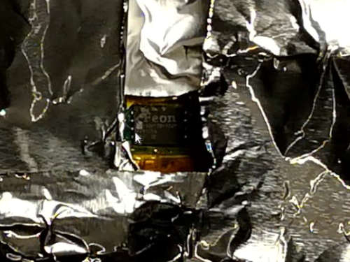
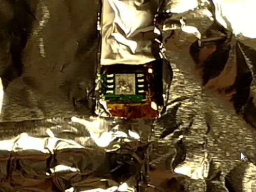
Surround a large area around the chip with layers of kapton tape, and then
|
|
aluminium foil. This will act as a heat shield, to reduce the risk of re-flowing
|
|
other solder joints (which can make them turn into cold joints, and you risk
|
|
knocking them off of the board):\
|
|
\
|
|
Notice that the kapton+foil does not cover the chip itself, or the solder pads.
|
|
It's important that these are exposed to the heat.
|
|
|
|
Use a hot air rework station, set to about 330-340C. The reason for the higher
|
|
temperature is because air doesn't conduct heat as efficiently as an iron, so
|
|
you must use a higher temperature. You should put lots of rosin flux above the
|
|
IC. Do not hold the nozel too close to the board. The diameter of the nozel
|
|
should be slightly higher than the length of the chip. Apply even heat, at high
|
|
air flow.
|
|
|
|
While blasting the chip with hot air, hold the chip with tweezers but do not
|
|
use any real force. Do not try to forcefully pry off the chip. Simply hold the
|
|
chip with your tweezers, gently nudging it until it feels like the chip can
|
|
move freely. While in this state, the solder is fully melted and the chip can
|
|
be lifted off with ease.
|
|
|
|
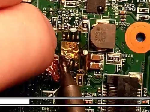
If you're doing it correctly, the chip will come off within 1 minute, like so:\
|
|
|
|
|
|
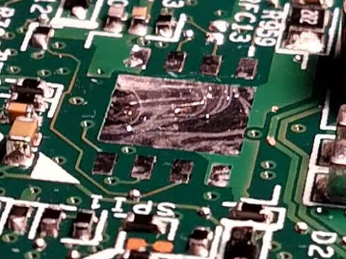
Add fresh solder to the pads, including the thermal pad:\
|
|
|
|
|
|
Now wick it out using a copper braid, dunked in rosin flux:\
|
|
|
|
|
|
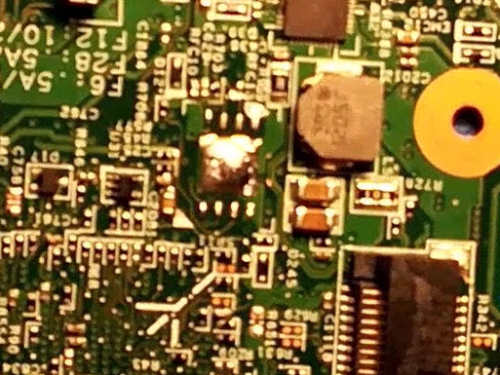
Ensure that all of the solder is removed:\
|
|
\
|
|
You will notice that one of the pads doesn't have all of the solder removed.
|
|
The pad on the top-left in this photo. This is intentional, to show you a
|
|
comparison for reference. The other pads are free of solder.
|
|
|
|
You *can* simply solder the chip unflashed, and flash it using a test clip.
|
|
Alternatively, you can put the SOIC8 in a socket on a breadboard, and flash it
|
|
before soldering it. If you wish to dump the contents of the WSON8, you can
|
|
put the removed WSON8 in a socket on a breadboard and dump it using your
|
|
SPI flasher.
|
|
|
|
Align the new SOIC8, and tack it in the corner pins. Then solder it fully. Use
|
|
lots of flux!\
|
|
\
|
|
A T12-D08 tip is being used in this photo, but a mini chisel, mini hoof or
|
|
knife (e.g. T12-K) tip would be ideal.
|
|
|
|
Ensure that all the joints are perfect. A good solder joint is shiny, and with
|
|
concave fillets where the solder has flowed. Observe:\
|
|
|
|
|
|
After you're done, use a soft bristle brush and 99.9% isopropyl alcohol to
|
|
break up the remaining flux, then soak up the flux using a cloth, while the
|
|
alcohol is still wet. 99.9% isopropyl is the best liquid to use, because it
|
|
evaporates quickly and it does not leave a corrosive residue.
|
|
|
|
-------------------------------------------------------------------------------
|
|
|
|
LICENSING
|
|
=========
|
|
|
|
This page is released under different copyright terms than most other pages
|
|
on this website.
|
|
|
|
This page and the photos on it are available under
|
|
[CC BY SA 4.0](https://creativecommons.org/licenses/by-sa/4.0/legalcode.txt)
|
|
Check the Git repository for history of who owns what part of the document.
|
|
|
|
Some of these resources originate from the *old* Libreboot git repository,
|
|
before Libreboot split into separate repositories that include its `lbmk`
|
|
repository.
|
|
|
|
Photos showing a BeagleBone Black are under the normal GNU Free Documentation
|
|
license like other pages and images on this website, or you can use them under
|
|
the CC-BY-SA 4.0 license if you wish (I, Leah Rowe, own all BBB photos shown
|
|
on this page, except for the one on the beaglebone website, and that one is
|
|
merely linked here, instead of being hosted on the av.libreboot.org server).
|
|
|
|
This version of the page is hosted in the `lbwww` git repository, with images
|
|
for it hosted in the `lbwww-img` repository (from libreboot).
|